15
MOTOR HOME ELECTRICAL INSTALLATION:
For proper installation it is necessary for you to have available the following tools which are not
provided in the kit:
12 volt DC continuity tester
Small wire cutter, wire stripper, wire terminal crimper
Electric drill, #7 drill bit, and 3/8 nut driver bit
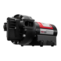
INSTALLATION OF ELECTRICAL MONITOR
(REFERENCE PAGE 18 FOR SCHEMATIC)
NOTE: A quick-disconnect plug has been manufactured into the back of the Electrical
Monitor. This allows for easy replacement of the unit should it become necessary.
Simply unplug the harness from the back of the monitor.
Step 1. Select a suitable location for the Electronic Monitor on the dashboard of the motor
home. The location should be suitable for the driver to both hear and see the monitor.
Screws are provided for mounting (4 - #6 self-tapping screws).
NOTE: THE MONITOR IS A VITAL WARNING DEVICE TO PROTECT THE
TRANSMISSION OF YOUR TOWED VEHICLE SHOULD SOMETHING
GO WRONG WITH THE LUBE PUMP SYSTEM. IT IS VERY IMPORTANT
THAT THE MONITOR BE MOUNTED IN A LOCATION THAT IS EASY
TO SEE AND HEAR IN CASE IT ALARMS. IF IT ALARMS, STOP THE
COACH IMMEDIATELY AND DETERMINE WHAT IS WRONG OR YOU
WILL DAMAGE YOUR TRANSMISSION.
Step 2. Turn the ignition key of the motor home to the ON position. Use a 12 volt DC
continuity lamp tester to identify an appropriate accessory ignition terminal
connection at the motor home engine fuse box. Switch the ignition key OFF and
ON to make certain that the terminal is “HOT” only when the ignition key is turned
ON. Be sure no other accessories will be sharing this connection.
Step 3. Cut the fused orange wire from the monitor to an appropriate length. Strip the end
of the wire ¼” and crimp a male tab terminal onto the wire. Connect the orange wire
to the ignition terminal located in step 2.