Renesas RA Microcontrollers EK-RA6M2 v1 – User's Manual
R20UT4578EU0102 Rev.1.02 Page 10 of 32
Jul.29.20
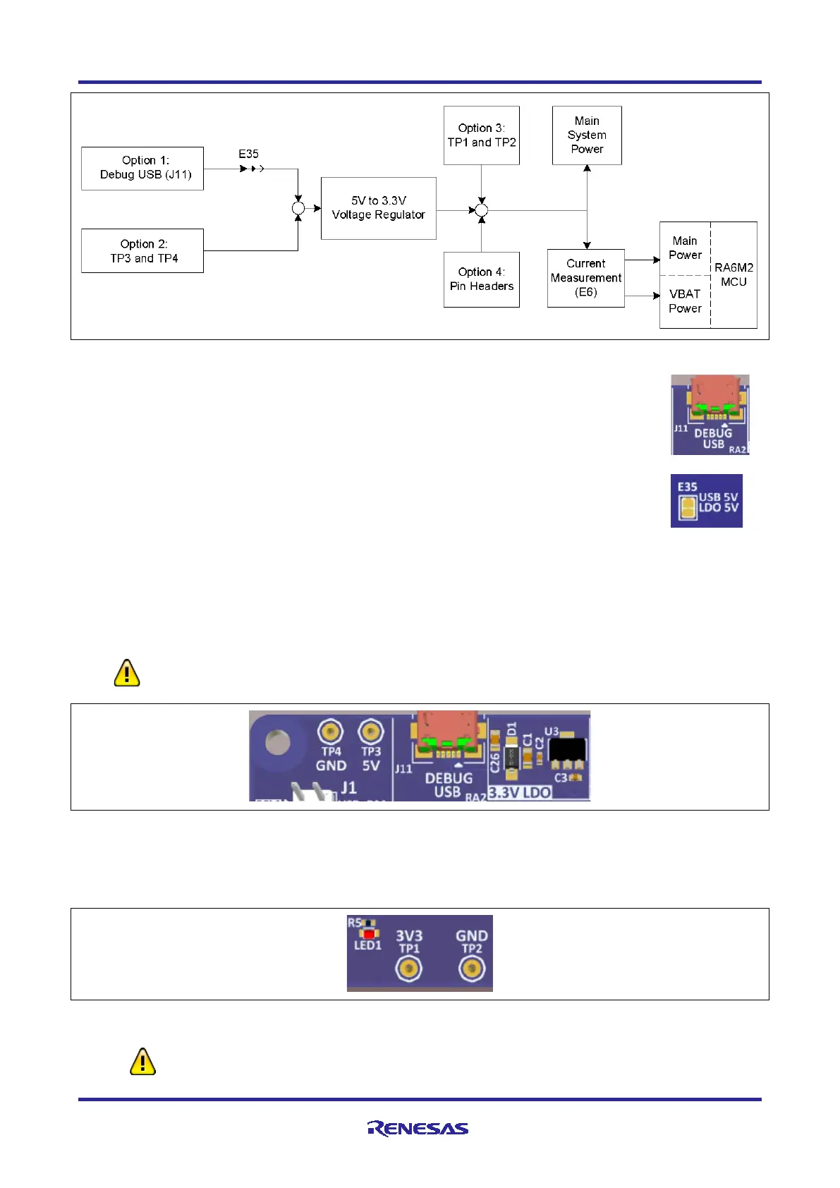
Figure 6. Power Supply Options
5.2.1.1 Option 1: Debug USB (default)
The default power source is 5 V, supplied from an external USB host to the USB Debug
connector labelled DEBUG USB on the top surface of the board. A low drop-out regulator
(LDO) is used to convert the 5 V signal to 3.3 V, which then is used to power the MCU and
any connected devices.
Copper jumper E35 selects the source for the primary power input to the LDO regulator. By
default, this jumper is configured to provide power through the Debug USB connector.
Copper jumper E35 is closed for this configuration.
5.2.1.2 Option 2: Test Points TP3 and TP4
The EK-RA6M2 board can also be powered by installing a 5 V power source across TP3 (positive input) and
TP4 (negative input). Copper jumper E35 must be opened to enable powering the board using these test
points.
The on-board Low Dropout Regulator (see section 5.3, Main Components) has an input
voltage range of +3.3 V to +5.5 V, and a built-in current limit of 600 mA. Make sure that any
external power source connected to TP3 and TP4 meets these requirements.
Figure 7. USB Debug Connector (J11), TP3, and TP4 on the Evaluation Kit Board
5.2.1.3 Option 3: Test Points TP1 and TP2
The EK-RA6M2 board can also be powered by installing a 3.3 V source across TP1 (positive input) and TP2
(negative input). Copper jumper E35 must be open to enable powering the board using these test points.
Figure 8. TP1, TP2, and LED1 on the Evaluation Kit Board
These test points supply voltage directly to the RA6M2 MCU, the S124 J-Link MCU,
and other on-board circuitry. Use caution to ensure that any voltage connected in this
manner meets the power requirements for the active features. Power sources that are

 Loading...


