Renesas RA Microcontrollers EK-RA6M2 v1 – User's Manual
R20UT4578EU0102 Rev.1.02 Page 14 of 32
Jul.29.20
• User LED
Lite-On, part number LTST-C191KRKT (LED1)
• User defined
• Single color red LED as needed for user environment
• User Potentiometer
Bourns, part number 3352T-1-1-3LF (POT1)
• User defined
• Provides variable resistance as needed for user environment
• Not populated by default
5.4 Connectivity and Settings
Throughout this section, feature configuration using copper jumpers is described. See section 4.1.1, Copper
Jumpers for information on using copper jumpers.
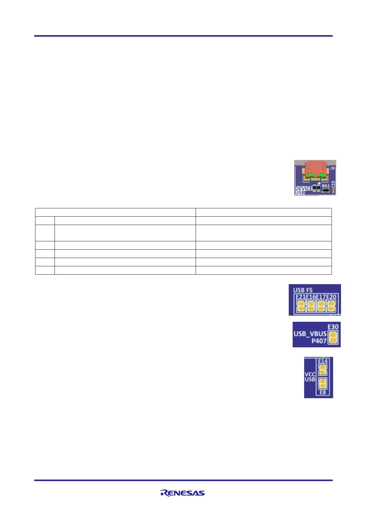
5.4.1 Device USB
The DEVICE USB Micro-B connection jack connects the Main MCU to an external USB
Host, FS capable, allowing communications for testing and use of the Main MCU firmware.
Power for the Evaluation Kit cannot be received from this connector. The DEVICE USB
interface can detect the presence of power from the USB Host PC. USB Host power
received at the DEVICE USB interface is not connected to the 5 V power bus.
Table 2. DEVICE USB Connector (J9)
+5VDC, connected to a sense voltage 2/3 divider
to allow Main MCU sensing of Host presence
+5VUSB
P407/USB_VBUS = 2/3(5VUSB)
USB ID, jack internal switch, cable inserted
USB FS copper jumpers E16, E17, E20, and E21 configure the connection between the
Device USB jack and the Main MCU. To allow use of the Device USB jack, copper jumper
E16 and E17 must be closed, and copper jumpers E20 and E21 must be open.
USB_VBUS copper jumper E30 configures P407 as a VBUS power detector. E30 is closed
by default to enable Device USB detection. To use P407 for any other purpose, E30 should
be open.
VCC USB copper jumpers E8 and E14 configure the source for the VCC USB power. To provide
VCC_USB from +3V3MCU, E8 must be closed. To isolate VCC_USB from +3V3MCU, E8 must
be open. To source +3V3MCU power from J1, or to monitor VCC_USB voltage from J1, E14
pads must be closed, otherwise, E14 should be left open.
The VCC_USB pin on the MCU (pin 40) is used to detect the presence of a USB connection.

 Loading...


