Renesas RA Microcontrollers EK-RA6M2 v1 – User's Manual
R20UT4578EU0102 Rev.1.02 Page 11 of 32
Jul.29.20
outside of the published operating range for the active devices may cause degraded
performance or damage the board.
5.2.1.4 Option 4: Pin Headers
EK-RA6M2 board can also be powered through the following pin-headers.
• J1 (pin J1-15 for +3.3 V, pin J1-17 for Return)
• J2 (pin J2-10 for +3.3 V, pin J2-12 for Return)
• J4 (pin J4-37 for +3.3 V, pin J4-36 for Return)
Copper jumper E35 must be open for any of these configurations.
The pin headers supply voltage directly to the RA6M2 MCU, the S124 J-Link MCU, and
other on-board circuitry. Use caution to ensure that any voltage connected in this
manner meets the power requirements for the active features. Power sources that are
outside of the published operating range for the active devices may cause degraded
performance or damage the board.
See section 5.5, Pin Headers for more information on the Pin Headers.
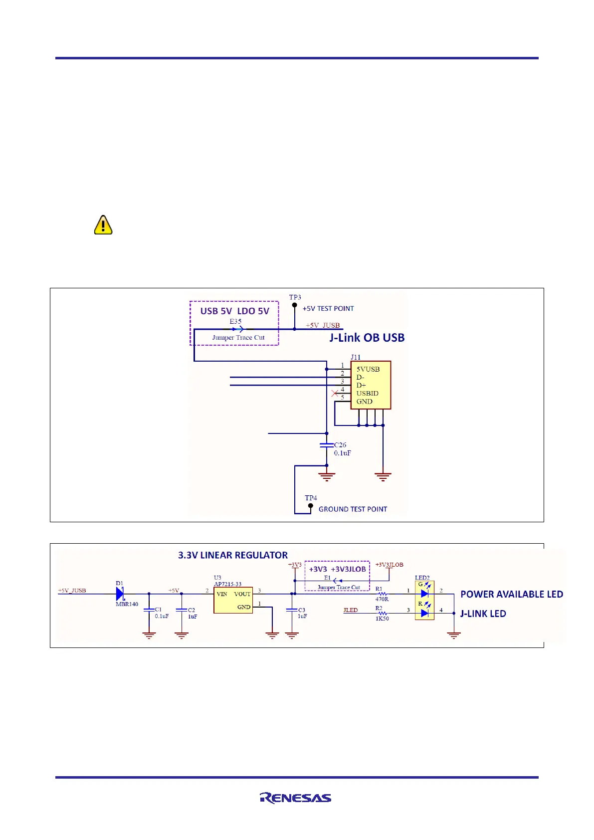
Figure 9. 5 V Power Input Circuit
Figure 10. 3.3 V Power Regulator Circuit
5.2.2 Powering up the Board
When powered, the green LED to the right of the DEVICE USB connector (LED2) lights up.
The red LED in the same LED package functions as a status indicator for the J-Link
®
On-Board (OB) debug
interface on the board. If both LEDs in the LED2 package are lit, LED2 appears orange.

 Loading...


