Renesas RA Microcontrollers EK-RA6M2 v1 – User's Manual
R20UT4578EU0102 Rev.1.02 Page 19 of 32
Jul.29.20
Table 10. PMOD A Connector (J5)
U1 P103, SSLA0_A (U1-105)
U1 P101, MOSIA_A (U1-107)
U1 P100, MISOA_A (U1-108)
U1 P102, RSPCKA_A (U1-106)
Limits of the 3.3 V regulator, and limits of the power source supplying that regulator (especially for USB Host
devices), including the to-be-connected PMOD device, must be considered prior to connecting a module to a
PMOD connector.
5.4.7 PMOD B
A 6-pin PMOD type 4 connector is provided at PMOD B. The interface is powered for
3.3 V modules only. The Main MCU acts as the UART DCE, and the connected module
acts as the UART DTE. This interface may additionally be re-configured in firmware as
some other PMOD type.
Signals on PMOD B are shared with Main MCU pin header J1 and J2. Care must be taken
to ensure that shared signals are not used concurrently.
Table 11. PMOD B Connector (J6)
U1 P400, GPIO (U1-1) (for RTS by Main MCU firmware)
Limits of the 3.3 V regulator, and limits of the power source supplying that regulator (especially for USB Host
devices), including the to-be-connected PMOD device, must be considered prior to connecting a module to a
PMOD connector.
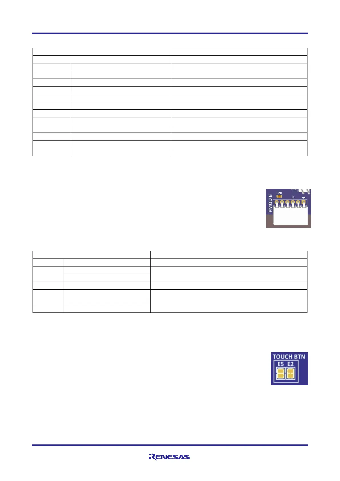
5.4.8 User Capacitive Touch Button
A capacitive sensor region for use as a Capacitive Touch button is provided in the board
USER INPUT region.
To disconnect the Capacitive Touch Button from the MCU, the copper jumper E2 must be
open.
To connect MCU signal P207 to pin header J3, the copper jumper E5 must be closed.
Note: Capacitor C33 is optional. This design does not include a dielectric overlay, so C33 is added to
reduce the sensitivity of the Capacitive Touch Button. This capacitor is not required by the MCU
specification.

 Loading...


