Renesas RA Microcontrollers EK-RA6M2 v1 – User's Manual
R20UT4578EU0102 Rev.1.02 Page 7 of 32
Jul.29.20
4. Hardware Details
4.1 Jumpers Settings
4.1.1 Copper Jumpers
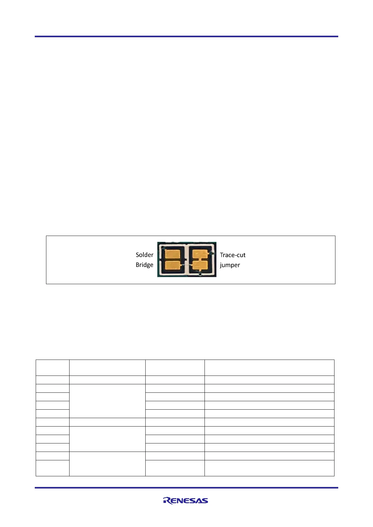
Copper jumpers are of two types, designated trace-cut and solder-bridge.
A trace-cut jumper is provided with a narrow copper trace connecting its pads. The silk screen overlay
printing around a trace-cut jumper is a solid box. To isolate the pads, cut the trace between pads adjacent to
each pad then remove the connecting copper foil either mechanically or with the assistance of heat. Once
the etched copper trace is removed, the trace-cut jumper is turned into a solder-bridge jumper for any later
changes.
A solder-bridge jumper is provided with two isolated pads that may be joined together by one of three
methods:
• Solder may be applied to both pads to develop a bulge on each and the bulges joined by touching a
soldering iron across the two pads.
• A small wire may be placed across the two pads and soldered in place.
• A SMT resistor, size 0805, 0603, or 0402, may be placed across the two pads and soldered in place. A
zero-ohm resistor shorts the pads together.
The silk screen overlay printing around a solder-bridge jumper is a box with a gap in the lines adjacent to the
isolation region between the pads.
For any copper jumper, the connection is considered closed if there is an electrical connection between the
pads (default for trace-cut jumpers). The connection is considered open if there is no electrical connection
between the pads (default for the solder-bridge jumpers).
Figure 4. Copper Jumpers
4.1.2 Default Board Configuration
The following table describes the default settings for each jumper on the EK-RA6M2. This includes traditional
pin jumpers (Jx designation) and copper jumpers (Ex designation).
The Circuit Group for each jumper is the designation found in the board schematic. See section 7, Design
and Manufacturing Information. Functional details for many of the listed jumpers may be found in section 5.4,
Connectivity and Settings and section 5.6, Additional Features.
Table 1. Default Jumper Settings
Sets the MCU Mode to boot from Internal Flash
12M XTAL
Connects signal P213 to MCU
Connects signal P212 to MCU
Connects 12.000 MHz Crystal to MCU
Connects 12.000 MHz Crystal to MCU
Alternate 3.3V source (+3V3JLOB)
Connects signal P215 to MCU
Connects 32.768 kHz Crystal to MCU
Connects 32.768 kHz Crystal to MCU
Capacitive Touch-Button
Enable/Disable Capacitive Touch-Button
Connects signal P207J to Capacitive Touch-
Button

 Loading...


