Renesas RA Microcontrollers EK-RA6M2 v1 – User's Manual
R20UT4578EU0102 Rev.1.02 Page 15 of 32
Jul.29.20
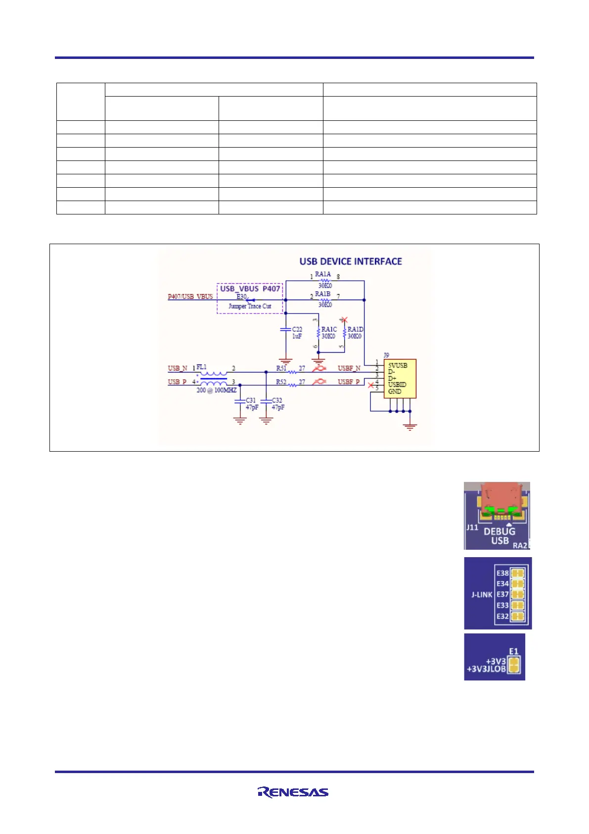
Table 3. USB Source Copper Jumper Settings
Jumper
Device USB
Micro-B Connector
Connect USB 5V to MCU P407
USB Micro-B 3.3V to MCU VCC_USB
P407 is also used by the Capacitive Touch interface.
Figure 15. USB Device Interface Circuit
5.4.2 Debug USB
The DEBUG USB Micro-B connection jack connects the S124 J-Link MCU to an external
USB Host, FS capable, allowing re-programming and debugging of the Main MCU
firmware. Power for the Evaluation Kit may be received from this connector.
The J-Link
®
OB interface is multiplexed with the JTAG interface, and can collectively be
referred to as the Programming Interface. While the J-Link OB interface and the JTAG
interface do not conflict, the J-Link OB signals may be isolated from the programming
interface by changing the associated copper jumpers.
J-Link Disconnect Copper Jumpers E32, E33, E34, E37, and E38, connect the J-Link
signals to the MCU programming interface. To isolate the J-Link signals from the JTAG
interface, the copper jumpers must be open. To allow use of the J-Link interface, each
copper jumper must be closed.
J-Link MCU Power Copper Jumper, E1, connects the main +3.3 V power to the J-Link
+3.3 V power. The default condition for E1 is closed, which connects the J-Link MCU
power to the main +3.3 V power. If J-Link signals are disconnected, the power to the J-Link
MCU should also be removed by changing E1 to open.

 Loading...


