Renesas RA Microcontrollers EK-RA6M2 v1 – User's Manual
R20UT4578EU0102 Rev.1.02 Page 27 of 32
Jul.29.20
Figure 28. User Potentiometer on the Evaluation Kit Board (top)
5.6.4 Boot Configuration
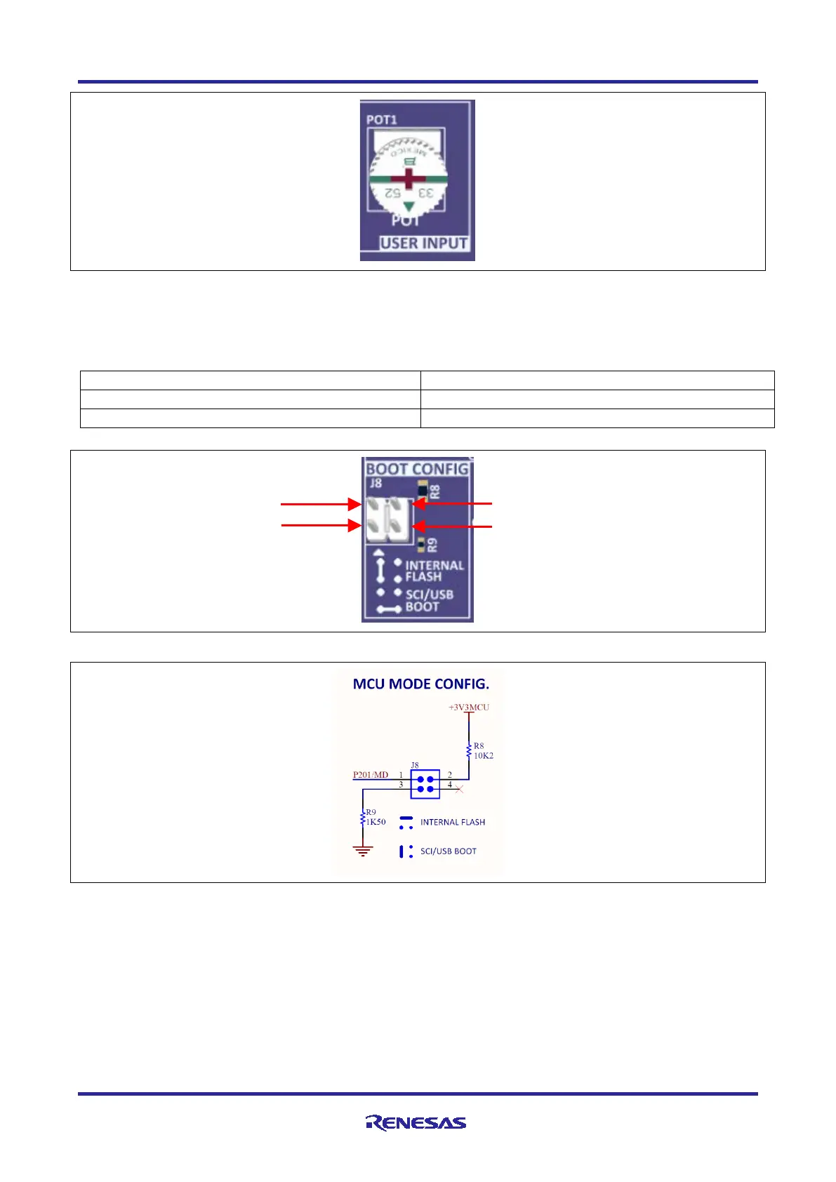
The BOOT CONFIG jumper, J8 is used to configure the operating mode of the RA6M2 MCU at boot.
Table 18. Boot Configuration
Figure 29. Boot Configuration Header
Figure 30. Boot Mode Configuration Circuit
5.6.5 Miscellaneous Signals
5.6.5.1 Analog Voltage AVCC0/AVSS0
By default, AVCC0 is connected to +3V3 MCU and AVSS0 is connected to the system ground. To
disconnect these references from the AVCC0 and AVSS0 lines, copper jumpers E10 and E11 must be open.
By default, VREFH is connected to +3V3MCU, and VREFL is connected to the system ground. To
disconnect these references from the VREFH and VREFL lines, copper jumpers E52 and E53 must be open.
Pin 2

 Loading...


