EasyManuals Logo

Renesas RTK79210**B00000BE User Manual

Renesas RTK79210**B00000BE
106 pages
To Next Page IconTo Next Page
To Previous Page IconTo Previous Page
Page #61 background imageLoading...
Page #61 background image
RZ/A2M SUB Board RTK79210XXB00000BE 3. Operating specifications
R20UT4398EJ0100 Rev.1.00 3-1
2018.10.11
3. Operating specifications
3.1 Overview of Connector
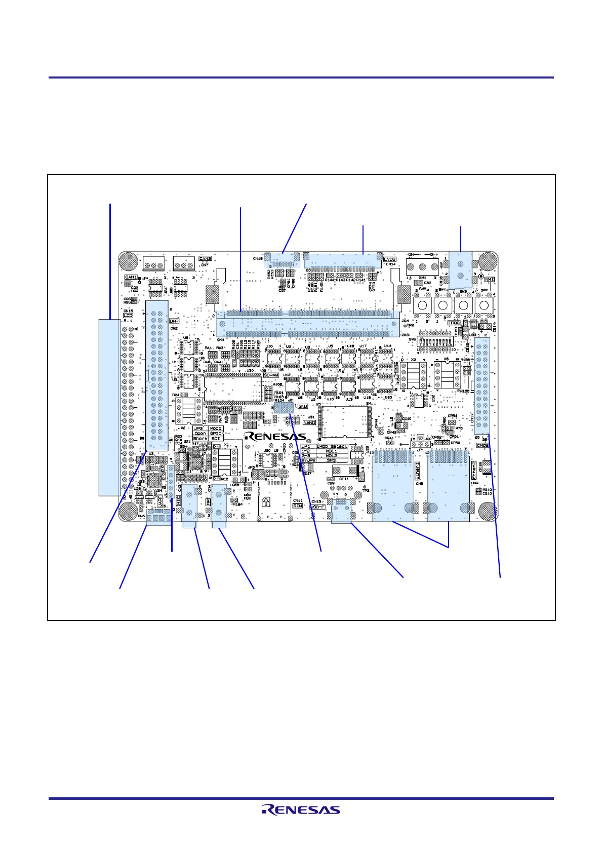
Figure 3.1.1 and Figure 3.1.2 show connector layout diagrams for RTK79210XXB00000BE.
Figure 3.1.1 RTK79210XXB00000BE Connector Layout Diagram (C Side Top View)
CN1: CPU board
Connector
CN2: DRP
connector
CN3: Mic in
Pin jack
CN5: Serial port connector
(USB Micro-B)
CN8, CN9:
LAN connector (RJ-45)
CN13: USB Mini-B
Port
CN14: LVDS
connector
CN15: Digital image signal
Input/output connector
CN16: LVDS back line
connector
J1: E1
connector
CN4: Line out
Pin jack
J2: GND connector
CN18: DC power
source jack
CN17: CMOS camera
connector

Other manuals for Renesas RTK79210**B00000BE

Questions and Answers:

Question and Answer IconNeed help?

Do you have a question about the Renesas RTK79210**B00000BE and is the answer not in the manual?

Renesas RTK79210**B00000BE Specifications

General IconGeneral
BrandRenesas
ModelRTK79210**B00000BE
CategoryComputer Hardware
LanguageEnglish

Related product manuals