EasyManuals Logo

Renesas RTK79210**B00000BE User Manual

Renesas RTK79210**B00000BE
106 pages
To Next Page IconTo Next Page
To Previous Page IconTo Previous Page
Page #83 background imageLoading...
Page #83 background image
RZ/A2M SUB Board RTK79210XXB00000BE 3. Operating specifications
R20UT4398EJ0100 Rev.1.00 3-23
2018.10.11
3.2.1 Jumpers (JP1 and JP2)
RTK79210XXB00000BE is equipped with two system setting jumpers.
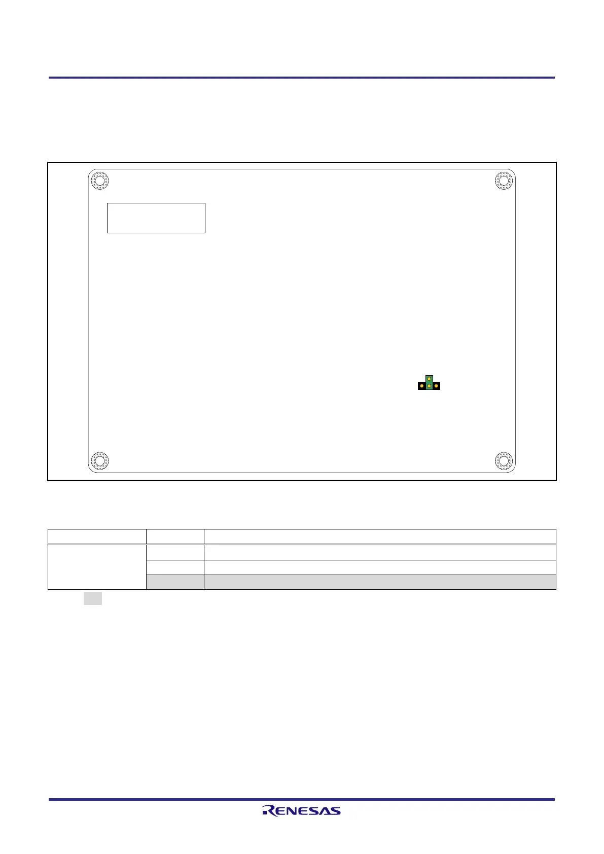
Figure 3.2.2 shows the jumper layout diagram, and Table 3.2.1 shows the jumper setting table.
Figure 3.2.2 RTK79210XXB00000BE Jumper Layout Diagram
Table 3.2.1 Jumper Setting Table (JP1 and JP2)
Jumper
Settings
Function
JP1
IRQ0 input selection
1-2
Ethernet PHY1 (U27) WOL pin
2-3
Ethernet PHY2 (U28) WOL pin
2-JP2
IRQ0 switch (SW3)
[Note] displayed during initial settings.
Be sure to turn off the power before altering the jumper settings.
JP1
1 3
JP2
C side top view

Other manuals for Renesas RTK79210**B00000BE

Questions and Answers:

Question and Answer IconNeed help?

Do you have a question about the Renesas RTK79210**B00000BE and is the answer not in the manual?

Renesas RTK79210**B00000BE Specifications

General IconGeneral
BrandRenesas
ModelRTK79210**B00000BE
CategoryComputer Hardware
LanguageEnglish

Related product manuals