repligen.com IF.UG.028 R1
6. Instructions for use
6.1 Installation and mechanical assembly
KrosFlo® Systems have a small footprint and require only a small clean area (approx. 3 m x 3 m/10 ft.
x 10 ft.) for assembly. No tools are needed for system assembly, though some basic hand tools such
as screw gun, pliers, and screwdrivers are needed to uncrate the system.
Some of the major components listed above are mounted on the cart. The other components can be
removed from boxes and installed on the cart for use in the process.
Follow these high-level steps to install and assemble the system:
1. Uncrate the system and remove all packaging material from the system components.
2. Locate and attach the proper filter brackets to the frame. The filter stand extension is
attached to the cart frame by attaching it to the filter post. Be sure to place a black rubber
gasket between the extension and frame post. Secure the extension with the provided metal
clamp and hand tighten, or with a wrench.
3. Place the Product Pump (P-02) on the lower cart frame. Connect the power and control
cables.
4. Place the Buffer Pump (P-03) on the cart frame. Connect the power and control cables.
5. The Recirculating Pump (P-01) will come already mounted. Consult the layout diagram
provided in the documentation package.
6. Install and connect scale (WE-01), or scale interface cable. If the tanks are more than one,
accordingly connect the scales as WE-02, WE-03 etc.
7. Route and connect all cables. Cables are marked based on their destination. All cables
should be routed to minimize kinking and obstructions.
8. Once the filter stand is assembled and pump motor is mounted, ready the pump head and
flow path/MBT assembly items. Make sure all necessary components to complete the
process line are available and ready (reactor, tubing, welding equipment, etc.). Please note
that the process assembly should be designed to minimize hold-up volume.
9. To prepare the pump head and flow path/MBT assembly:
a. Carefully support the MBT/filter/pump head assembly and hold at an angle such
that the pump head discharge lines up with the green color band at the pump
support on the end of the motor drive.
b. Install the pump head into the pump motor drive making sure to disengage/pull out
the locking pin to fully seat the pump head.
c. Rotate the pump discharge port and filter assembly to the vertical position and
towards the red color band on the pump drive. The locking pin will click into place
when the pump head is properly oriented in the pump drive.
d. Locate the filter in the 2 filter clamps on the frame post, making sure the clamps
attach to the filter on the clear section of the housing (not on end fittings). Inspect
the filter and pump before tightening clamps in place; there should be no strain
placed upon any of the filter, pressure sensor or pump connections.
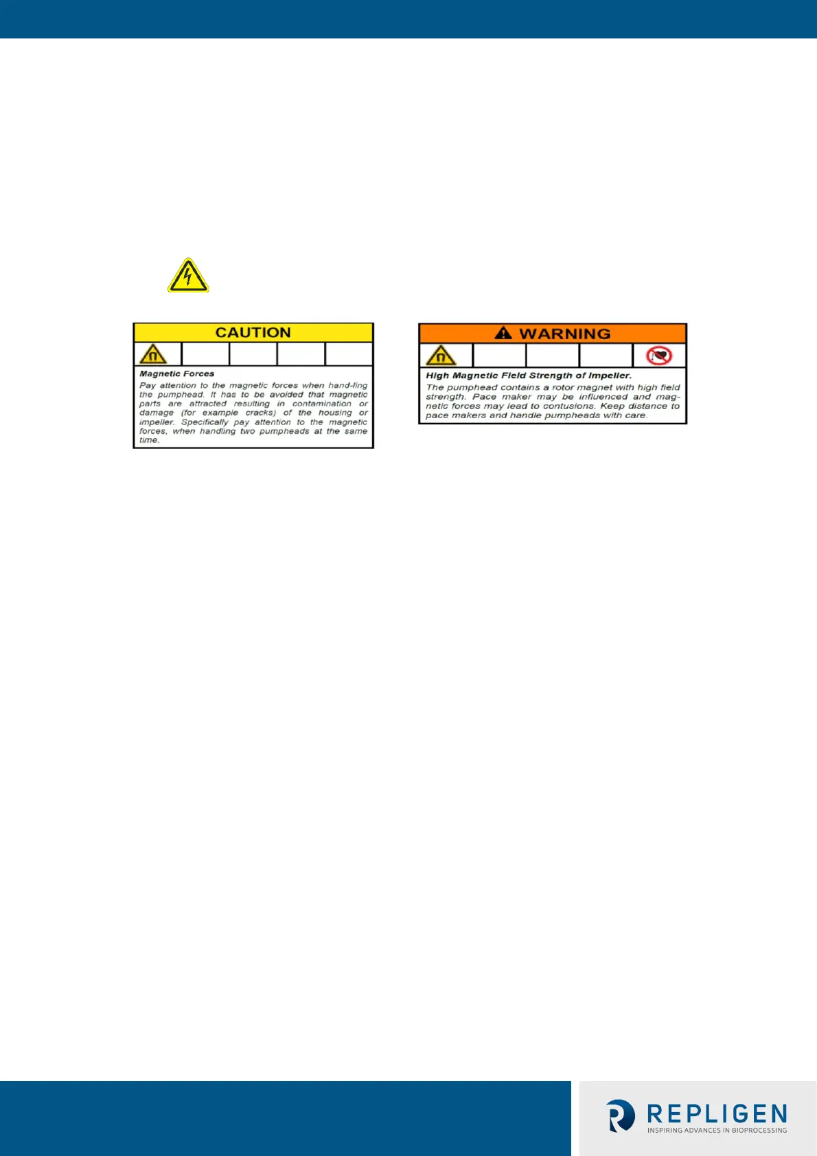
WARNING – Do not plug in the system during Mechanical
Assembly.