DeltaSol
®
BS
© RESOL 04272 deltasol_bs.mon.pmd
7 |
1
3
2
backwards
forward
SET
(selection / adjustment mode)
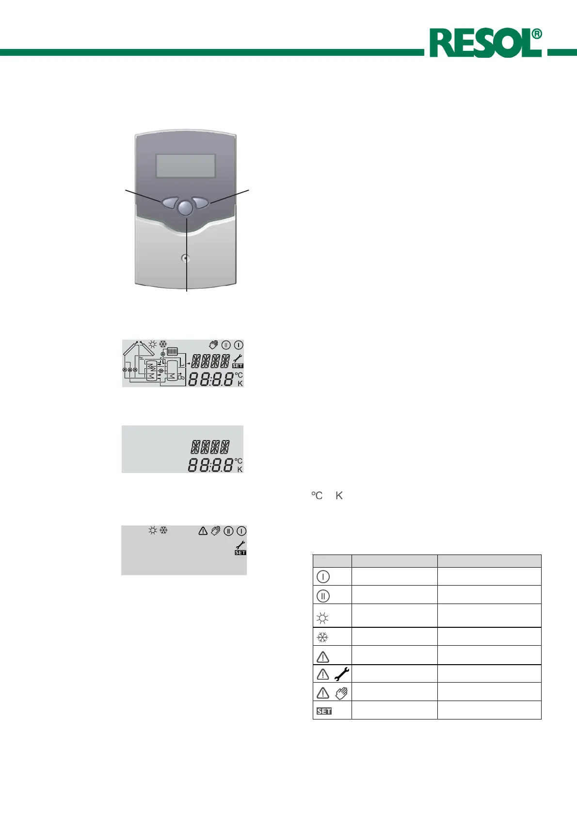
The system monitoring display consists of 3 blocks:
indication of the channel, tool bar and system screen
(active system scheme).
The indication channel consists of two lines. The upper
line is an alphanumeric 16-segment indication, in which
mainly the channel names / menu items are shown. In the
lower 7-segment indication, the channel values and the
adjustment parameter are indicated.
Temperatures and temperature differences are indicated in
or .
2.2.1 Channel indication
only channel indication
2.2.2 Tool bar
The additional symbols of the tool bar indicate the current
system status.
only tool bar
2. Operation and function
2.1 Pushbuttons for adjustment
The controller is operated by 3 pushbuttons below the
display. The forward-key (1) is used for scrolling forward
through the indication menu or to increase the adjustment
values. The backwards-key (2) is accordingly used for the
reverse function.
For adjustment of last indication channel, keep button 1
pressed for 2 seconds. If an adjustment value is shown
on the display, SEt is indicated. In this case you can press
the key „Set“ (3) in order to change into input mode.
Select a channel by keys 1 and 2
Shortly press key 3, so that „SEt“ flashes
Adjust the value by keys 1 and 2
Shortly press key 3, so that „SEt“ permanently appears,
the adjusted value is now saved.
2.2 System monitoring display
!
ê
$
$
Complete Monitoring-Display
+
+
symbol standard flashing
relay 1 active
relay 2 active
maximum store limitation
active / maximum store
temperature exceeded
collector cooling function active
reccoling function active
option antifreeze function
active
collector minimum limitation active
antifreeze function active
collector security shutdown active
or store securtiy shutdown active
sensor defect
manual operation active
an adjustment channel is changed
SET-mode

 Loading...