DeltaSol
®
BS
© RESOL 04272 deltasol_bs.mon.pmd
5 |
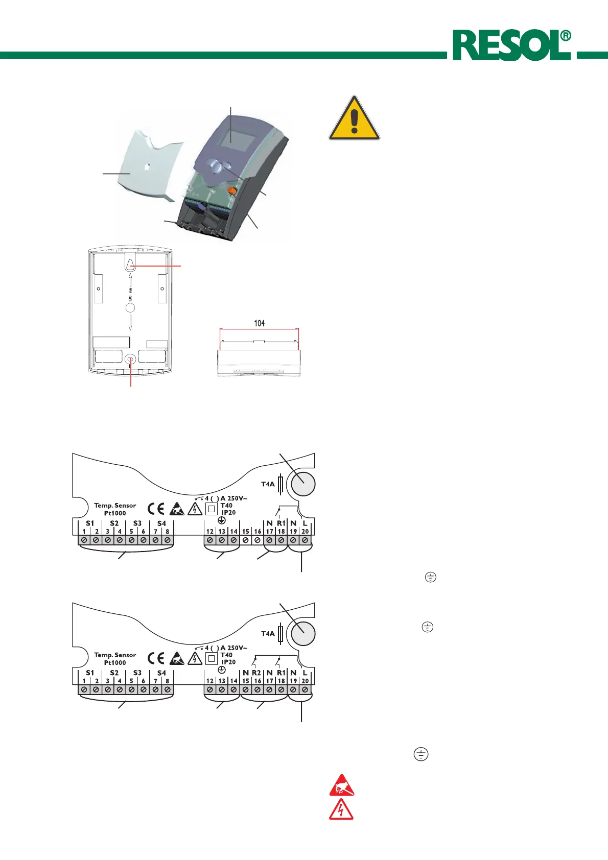
display
pushbutton
can fuse 4A
cable conduits with strain
relief
cover
2
1.1 Mounting
The unit must only be located internally. It is not suitable
for installation in hazardous locations and should not be
sited near to any electromagnetic field. The controller must
additionally be equipped with an all-polar gap of at least 3
mm or with a gap according to the valid installaton
regulations, e.g. LS-switches or fuses. Please pay attention
to a separate laying of the cable lines and installation of ac
power supply.
1. Unscrew the cross-recessed screw of the cover and
remove it from the housing.
2. Mark the upper fastening point on the wall and premount
the enclosed dowel and screw.
3. Hang up the housing at the upper fastening point and
mark the lower fastening point on the underground (hole
pitch 130 mm), afterwards put the lower dowel.
4. Fasten the housing at the underground.
1. Installation
Warning!
Switch-off power supply before
opening the housing.
1.2 Electrical wiring
The power supply to the controller must only be made by
an external power supply switch (last step of installation!)
and the line voltage must be 210 ... 250 Volt (50...60 Hz).
Flexible lines are to be fixed at the housing by enclosed
strain relief supports and screws.
Depending on the version the controller is equipped with
1 relay (PG 66.30 and PG 67.30) or 2 relays (PG 68.30 and
PG 69.30) to which the consumers e.g. pumps, valves etc.
can be connected:
• Relay 1
18 = conductor R1
17 = neutral conductor N
13 = ground clamp
• Relay 2 (
PG 68.30 and 69.30
)
16 = conductor R2
15 = neutral conductor N
14 = ground clamp
The temperature sensors (S1 up to S4) will be connected
to the following terminals independently of the polarity:
1 / 2 = Sensor 1 (e.g. Sensor collector 1)
3 / 4 = Sensor 2 (e.g. Sensor store 1)
5 / 6 = Sensor 3 (e.g. Sensor TSPO)
6 / 7 = Sensor 4 (e.g. Sensor TRL)
The power supply is effected to the clamps:
19 = neutral conductor N
20 = conductor L
12 = ground clamp
net clamps
fuse
consumer clamps
Sensor clamps
hanging
fixation
earthing clamps
Electrostatic discharge can lead to damages of
electronic components!
Dangerous voltage on contact!
Please note:
The relays are semi-conductor-relays for pump speed control - they
need a minimum load of 20 W (power consumption of the consumer)
for faultless function. If auxiliary relays, motor valves, etc. are connected,
the condenser which is enclosed in the mounting material, must be
connected parallely to the relevant relay output.
Attention: for connection of auxiliary relays or valves, the minimum
pump speed must be adjusted to 100 %.
2
net clamps
fuse
consumer clamps
Sensor clamps
earthing clamps
PG 66.30 and 67.30
PG 68.30 and 69.30

 Loading...