4
NOTE: Move all parts to
the desired work site before
assembling them together. Follow
the assembly instruction and
carefully assemble the tool with the help of
a second person.
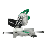
TRANSPORTING THE SAW (FIG. 1)
To avoid damage, never carry the miter saw
by the switch handle, the cutting arm or the
miter handle. ALWAYS use the designated
carrying handle (24). (Fig. 1)
To lock the cutting head: When transporting
or storing the miter saw, the cutting head
should always be locked in the down position.
1. Press the cutting head down to its
lowest position.
2. Push the head hold-down latch (22) into
the locking hole.
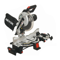
CUTTING HEAD (FIG. 2)
Raising the cutting head:
To unlock the cutting head from the
collapsed position:
1.
Push down the switch handle (1) slightly.
2. Pull out the head hold-down latch (2).
3. Raise the cutting head to the uppermost
position.
NOTE: This cutting head is spring loaded.
WARNING! For your own safety, never
connect the plug to power source outlet
until all assembly steps are completed
and you have read and understood the
safety and operational instructions.
Assembly
Specication
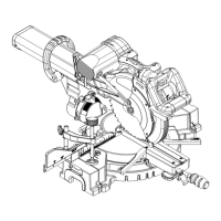
KNOW YOUR MITER SAW (FIG. 1)
1. ON/OFF trigger switch handle
2. Safety lock
3. Upper blade guard
4. Dust bag
5. Hold-down clamp
6. Mounting hole
7. Table insert
8. Base
9. Positive stop lock lever
10. Blade
11. Cover plate
12. Motor
13. Motor brush cap
14. Arbor lock button
15. Lower blade guard
16. Fence
17. Left extension wing
18. Table
19. Miter handle
20. Miter scale
21. Right extensition wing
22. Hold-down latch
23. Blade wrench
24. Carrying handle
Motor ..................... 2000 W, 220 V~ 50 Hz,
Double Insulation
No load speed .......................... 4,500 min
-1
Blade ................Ø255 mm; Ø25.4 mm Bore
Turn table .................................... Ø280 mm
Miter stops .............0° ,15°, 22.5°, 31.6°, 45°
left & right
Miter angle range ................ 47° left & right
Maximum capacity
Cross cut ................................. 67×130 mm
Miter cut at 45° (R & L)............... 67×90 mm
Installation
WARNING! To avoid injury and damage
to the saw, transport and store the miter
saw with the cutting head locked in
the down position. Never use the stop
latch to hold the cutting head in a down
position for cutting operations.