Rexroth IndraDrive C Electrical Data 6-3
DOK-INDRV*-HCS02.1****-PR02-EN-P
6.3 Power Section – DC Bus Power
Designation Symbol Unit HCS02.1E-
W0012
HCS02.1E-
W0028
HCS02.1E-
W0054
HCS02.1E-
W0070
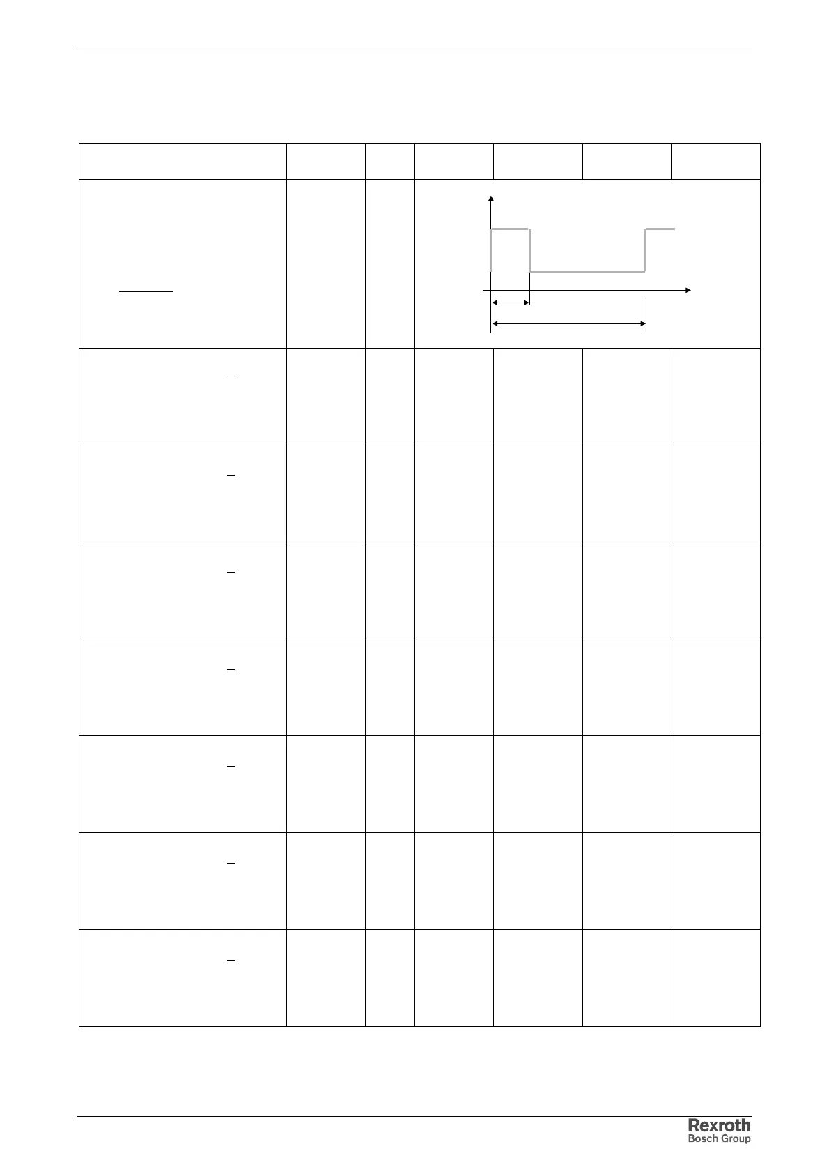
Profile DC bus power
overload operation
overload capacity:
base DC_
DC_peak
P
P
=K
T
P
DC_base
t
P
P
DC_peak
t
DC bus peak power
U
N1
= 3 x AC 400 V, at Ta<40 °C;
t=0.4 s; T=4 s
without mains choke
with mains choke
P
DC_peak_1
kW
5
5
8
10
12
16
14
19
DC bus power
U
N1
= 3 x AC 400 V, at Ta<40 °C;
t=0.4 s; T=4 s
without mains choke
with mains choke
P
DC_base_1
kW
1.5
1.5
4.7
4.2
6.2
9.1
8.3
13.3
DC bus peak power
U
N1
= 3 x AC 400 V, at Ta<40 °C;
t=2 s; T=20 s
without mains choke
with mains choke
P
DC_peak_3
kW
5
5
8
10
12
16
14
19
DC bus power
U
N1
= 3 x AC 400 V, at Ta<40 °C;
t=2 s; T=20 s
without mains choke
with mains choke
P
DC_base_3
kW
1.5
1.5
4.7
4.2
6.2
9.1
8.3
13.3
DC bus peak power
U
N1
= 3 x AC 400 V, at Ta<40 °C;
t=60 s; T=5 min
without mains choke
with mains choke
P
DC_peak_4
kW
4
4
8
10
12
16
14
19
DC bus power
U
N1
= 3 x AC 400 V, at Ta<40 °C;
t=60 s; T=5 min
without mains choke
with mains choke
P
DC_base_4
kW
1.2
1.2
4.1
2.7
5.0
7.8
7.2
12.4
DC bus peak power
U
N1
= 3 x AC 400 V, at Ta<40 °C;
t=60 s; T=10 min
without mains choke
with mains choke
P
DC_peak_5
kW
5
5
8
10
12
16
14
19
 Loading...


