15
I-UEZ (04-21) 1034347-0
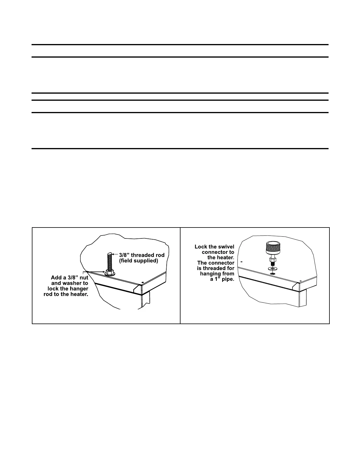
Figure 6. Heater Suspension
Suspension of Heater with Downturn Nozzle
Downturn nozzle kits (option CD2, CD3, or CD4) require four-point suspension. Follow the instructions provided
with the kit to install.
DETAIL A
DETAIL B
Heater Suspension
⚠ WARNING ⚠
• Before suspending the heater, check the supporting structure to be used to verify that it has
sufficient load-carrying capacity to support the weight (refer to Weights section) of the unit.
• The heater must be level for proper operation. DO NOT place or add additional weight to a
suspended heater.
⚠ CAUTION ⚠
• Before lifting the heater, verify that any screws used for holding shipping brackets were re-
installed in the cabinet.
• When the heater is lifted for suspension, support the bottom of the heater with plywood or other
appropriately placed material. If the bottom is not supported, damage could occur.
The heater is designed to be suspended using four-point suspension by one of the following methods:
1. Suspending heater using field-supplied 3/8-inch threaded rods (see Figure 6, DETAIL A):
a. A 3/8-16 threaded nut retainer is located at each suspension point.
b. Install 3/8-inch nut and washer to lock heater to threaded rod at each suspension point. Ensure that threaded
rod does not extend into heater more than 1/2 inch (13 mm). Recommended rod length is 6 feet (1.8 meters).
2. Using swivel connectors to suspend heater from 1-inch pipes (see Figure 6, DETAIL B):
a. Lock threaded swivel connectors (option CK10) to heater at 3/8-16 threaded nut retainers.
b. Swivel connectors are threaded to suspend heater from 1-inch pipe.

 Loading...


