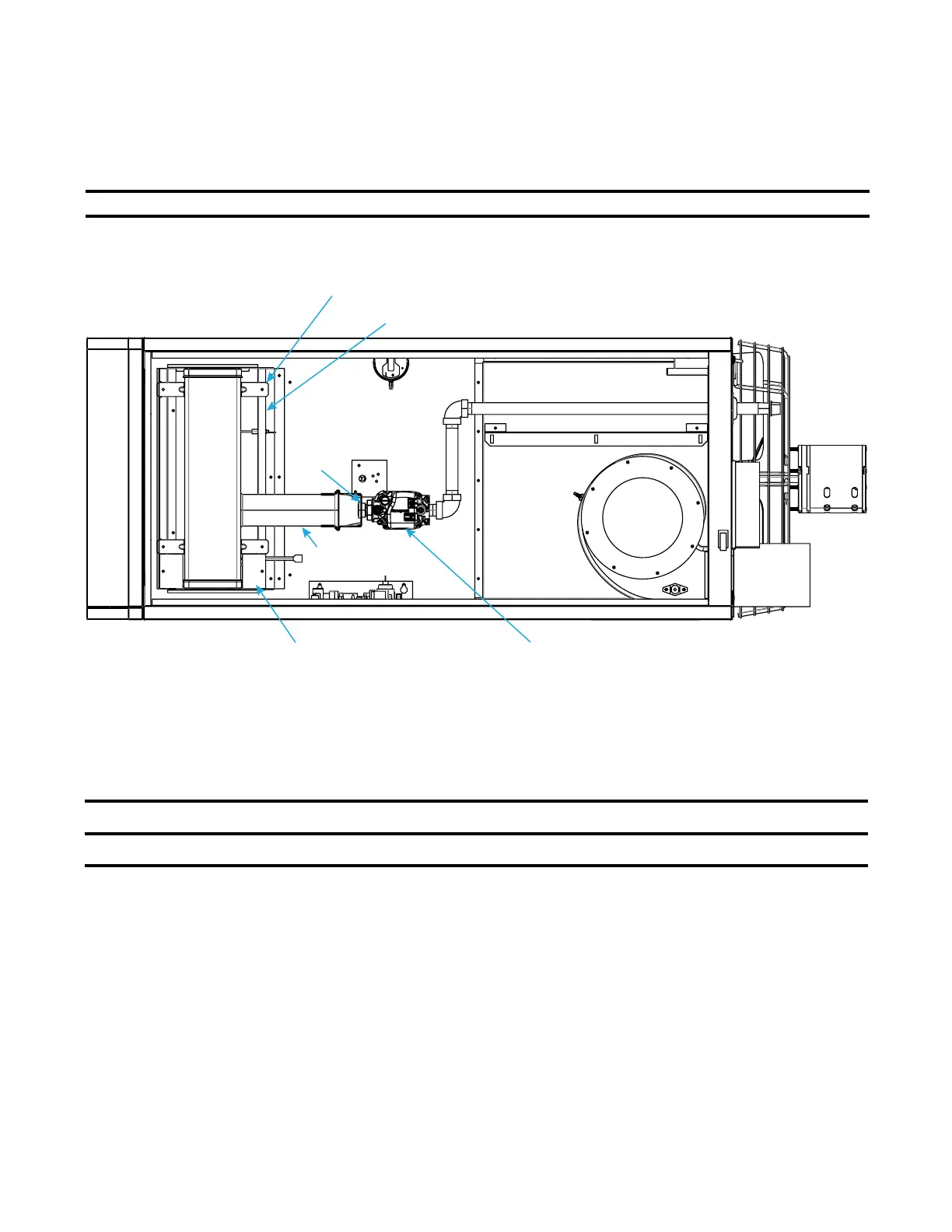
Figure 29. Burner Assembly
1. Remove gas and electric supply:
a. Shut OFF gas supply ahead of union at manual valve outside cabinet.
b. Turn OFF electric supply.
c. Disconnect gas supply at union outside of cabinet.
⚠ WARNING ⚠
Use of eye protectection is recommended.
2. Remove burner assembly (see Figure 29):
a. Remove access panel.
a. Detach gas train:
(1) Mark and disconnect wires at gas valve.
(2) Carefully remove burner orifice and orifice adapter locking nut.
(3) Slide orifice adapter out through bracket on burner while pushing gas train to right. This will move gas
train out of way.
b. Detach control assembly:
(1) Remove two screws that secure control assembly bracket.
(2) Being careful not to disconnect any wires, slide control assembly to right.
GAS VALVE
ORIFICE
ADAPTER
LOCKING
NUT
VENTURI TUBE
BURNER ASSEMBLY
SECONDARY AIR BAFFLE
SECONDARY AIR SHIELD
BURNER BODY SUPPORT
MAINTENANCE—CONTINUED
Maintenance Procedures
Burner Maintenance
NOTE: The unit is equipped with a TCORE
2
® burner.
Visually inspect the burner compartment (see Figure 29). If there is an accumulation of dirt, dust, and/or lint,
clean the compartment and remove and clean the burner as follows:
48
I-UEZ (04-21) 1034347-0

 Loading...


