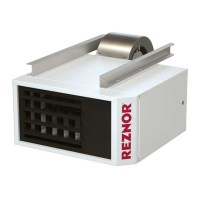
Figure 25. Component Locations
Thermostat Options
NOTES:
• IMPORTANT: all units MUST be operated by a 24V thermostat. Never use a line voltage disconnect
switch as a means of operating the heater.
• For all availaible thermostat and thermostat accessory options, contact contact an authorized
Factory Distributor.
• Install an optional thermostat (available with the heater) or a field-supplied 24V thermostat in accordance with the
thermostat manufacturer’s instructions. Pay particular attention to the requirements regarding the location of the
thermostat.
• Ensure that if there is a heat anticipator setting on the thermostat, it is set at 0.6 amps or in accordance with the
amperage value noted on the heater wiring diagram.
• Make thermostat connections at the terminal strip on the back of the heater (see Figure 23). The strip has five
terminals: C, R, G, W1, and W2. Refer to the wiring diagram provided with the heater.
• If the heater was ordered with a multiple heater control option, one thermostat can be used to control up to six
VENTER
MOTOR
MAIN OPERATING
GAS VALVE
HIGH TEMPERATURE LIMIT CONTROL
VENT TEMPERATURE
LIMIT SWITCH
DETAIL A
PRESSURE SWITCH
FLAME
SENSOR
FAN
MOTOR
IGNITOR
INTERLOCK
DOOR
SWITCH
DISCONNECT
SWITCH
DETAIL A
TRANSFORMER
DSI CONTROL MODULE
CONTROLS—CONTINUED
34
I-UEZ (04-21) 1034347-0

 Loading...