OPERATION—CONTINUED
Post-Startup Checklist
Check the following after startup:
Ensure that vent system has been tested in accordance with Vent System Testing section
With unit in operation, measure manifold (outlet) gas pressure in accordance with Measure and Adjust Manifold
(Outlet) Gas Pressure section
Turn unit OFF and ON, pausing 2 minutes between each cycle; observe for smooth ignition
Place literature bag that contains Limited Warranty, this manual, venting instructions, and any control or optional
information in accessible location near heater
⚠ DANGER ⚠
• The gas burner in this gas-fired equipment is designed and equipped to provide safe controlled
complete combustion. However, if the installation does not permit the burner to receive the
proper supply of combustion air, complete combustion may not occur. The result is incomplete
combustion, which produces carbon monoxide, a poisonous gas that can cause death. Safe
operation of indirect-fired gas burning equipment requires a properly operating vent system that
vents all flue products to the outside atmosphere. FAILURE TO PROVIDE PROPER VENTING WILL
RESULT IN A HEALTH HAZARD THAT COULD CAUSE SERIOUS PERSONAL INJURY OR DEATH.
• Always comply with the combustion air requirements listed in the installation codes and in
this manual. Combustion air at the burner should be regulated only by manufacturer-provided
equipment. NEVER RESTRICT OR OTHERWISE ALTER THE SUPPLY OF COMBUSTION AIR TO
ANY HEATER. MAINTAIN THE VENT OR VENT/COMBUSTION AIR SYSTEM IN STRUCTURALLY
SOUND AND PROPER OPERATING CONDITION.
ADJUSTMENTS
After startup, the gas valve outlet pressure must be measured and adjusted if necessary in accordance with the
Measure and Adjust Manifold (Outlet) Gas Pressure section. If the heater is being installed at an elevation of >6,000
feet (>1,830 meters), the pressure switch must be replaced in accordance with the Pressure Switch Replacement
section before the gas pressure is adjusted.
Pressure Switch Replacement
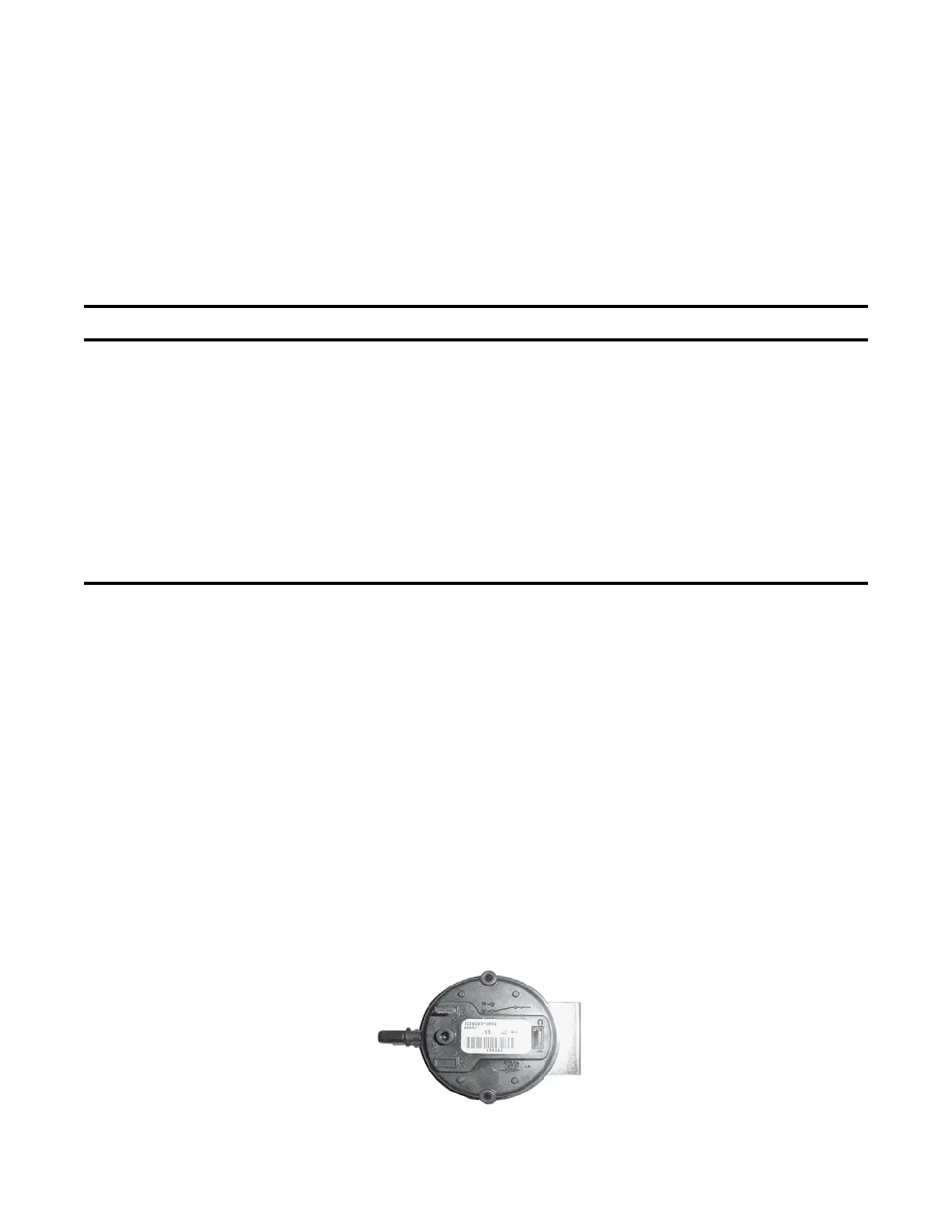
For installations at elevations >6,000 feet (>1,830 meters), the pressure switch (see Figure 27) must always be
replaced before the heater is operated. If ordered with the unit as part of a high-elevation kit (option DJ20 or DJ21),
the switch is shipped separately for field-installation. Replace the pressure switch as follows:
1. Locate pressure switch in control compartment (see Figure 25) and mark and disconnect two switch wires.
2. Mark and disconnect sensing tube(s) from pressure switch.
3. Remove two screws that secure mounting bracket and remove bracket and pressure switch. Save bracket and
screws for reuse.
4. Install replacement pressure switch (refer to replacement parts manual listed in Table 1 for PN) using mounting
bracket and two screws. Reconnect sensing tube(s) and wires.
Figure 27. Pressure Switch
42
I-UEZ (04-21) 1034347-0

 Loading...


