CONTROLS—CONTINUED
Vent Temperature Limit Switch
⚠ WARNING ⚠
If the manual vent temperature switch activates, identify and correct the cause before resetting the
switch. Never bypass the vent temperature switch as hazardous conditions could result.
All units are equipped with a temperature-activated, manual-reset switch to limit the temperature of vent gases to
below 145°F. The switch is attached to the side of the combustion air venter housing (see Figure 25 for location).
If the setpoint is reached, the switch interrupts the electric supply to the gas valve. If the switch is activated, identify
and correct the cause before resetting the switch.
Interlock Door Switch
All units are equipped with an interlock door switch (see Figure 25 for location) that prevents the heater from operating
when the service door panel is open. The service panel is equipped with a pliable gasket that fully seals the door to
provide added protection to prevent building air from entering the combustion zone of the heater.
Fan Motor
The fan motor is equipped with automatic-reset thermal overload protection. If the motor does not run, the cause
may be due to improper current. Ensure that the correct voltage is available at the motor.
Circuit Board (DSI Control Module)
The heater’s ignition system is controlled by a circuit board (Direct-Spark Integrated (DSI) control module, see
Figure 24) that monitors the safety devices and controls the operation of the fan and venter motors and the gas
valve between heat cycles. To view the Seven-Segment Display (SSD), the door panel requires removal. In addition,
there is a status LED on the bottom of the heater. Its status indications are off (heater is not powered or control board
fault), steady on (heater is on with no faults), or flashing (heater is on with fault(s)). Additional status indications
appear on the display at the bottom of the control module (labeled as DSP1, see Figure 24). The display’s codes
are listed and described in Table 19.
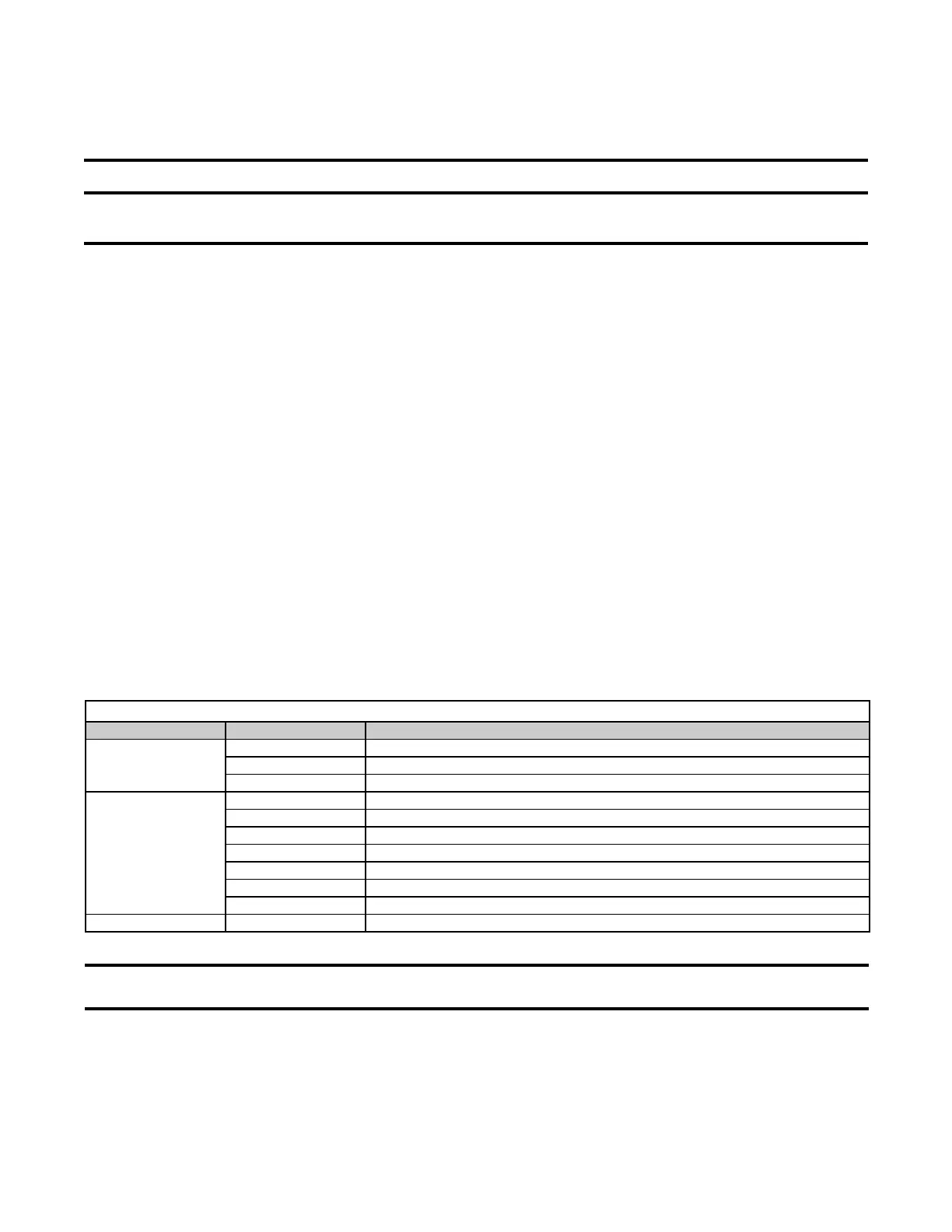
Table 19. Circuit Board (DSI Control Module) Display Codes
Display Code Status Display Code Indication
Steady
— Normal operation—no call for heat
0 Ignition sequence active
H Normal operation—call for heat (strong flame)
Flashing
2 Normal operation—call for heat (weak flame)
L Lockout from failed ignition or flame loss
3 Pressure switch is not closed within 30 seconds of venter motor energizing
4 Pressure switch is closed before venter motor is energized
5 Limit switch or rollout open
6 Undesired flame
7 Polarity reversed
Steady Off Internal fault/power failure
NOTE: Remove and reapply power to the control module to view the last five fault codes stored
in its memory. The most recent to least recent fault codes will be displayed.
Venter Motor
The venter motor (see Figure 25 for location) is assembled to the venter wheel and operates to provide combustion
airflow. Operation is controlled by the circuit board (see Figure 24). Refer to the Circuit Board (DSI Control Module)
section for details.
36
I-UEZ (04-21) 1034347-0

 Loading...


