Form I-MAPSIII&IV, Page 14
5.4.1.2 Roof Curb for MAPS
®
III&IV A, B, and C Cabinet with Vertical (Down) Airow WITH an
Optional Energy Recovery Module, Option ER1A, ER1B, ER1C (Roof Curb Option CJ34)
Roof Curb P/N by Model/Size
See Model
Size / Cabinet
Size Cross
Reference on
pages 71-72.
Cabinet A Cabinet B Cabinet C
RCB/RCC/RDB/RDC w/Option ER1 - All Cabinet A - - All Cabinet B
190, 216, 248,
262, 272, 288
-
298, 410, 354,
370, 468, 482
-
RDCB/RDCC/RDDB/RDDC w/Opt ER1 100 150 200 250 300 400 500 600 700
RECB/REDB/RECC/REDC w/Opt ER1 - All Cabinet A - - All Cabinet B - - All Cabinet C -
Roof Curb (Option CJ34) Package P/N 262478 262479 262480 262481 262482 262483 262484 262485 262486
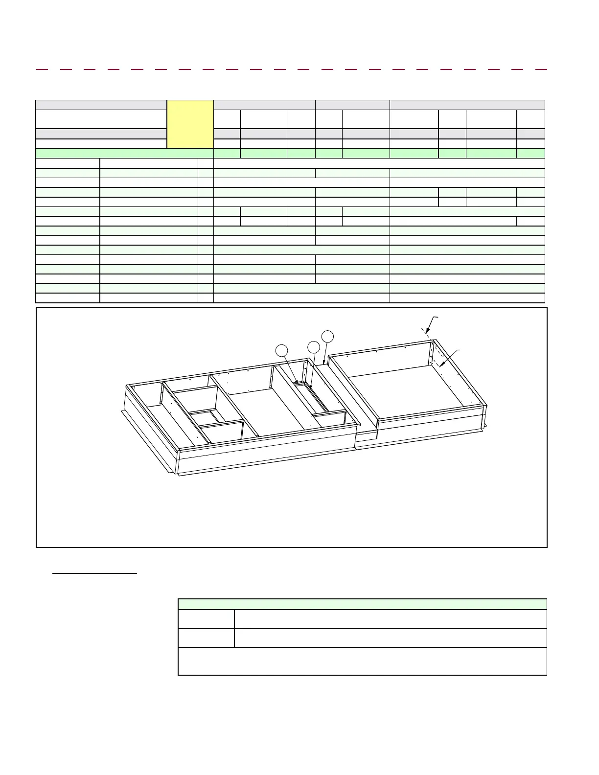
Code (FIGURE 8A) Component Description: Qty Component P/N's
A Curb Ends (unit & ER end) 2 204486 204487 208799
B Curb Sides (under unit) 2 204485 208798
C1 Supply Air Duct End 1 204431 204432 207961 207960 207959 207958
C2 Supply Air Duct End 1 204431 204432 207965 207964 207963 207962
D1 Supply Air Duct Side 1 204433 204434 204436 204435 204437 207967
D2 Supply Air Duct Side 1 204433 204434 204436 204435 204437 207967 207971
E Return Duct End 1 204438 204439 207966
F Return Duct Side 1 204440 204441 207974
G Return Duct Side Angle 1 204444 207973
H Return Duct Rear Angle 1 204442 204443 207972
J Curb End (unit end in center) 1 261995 261996 260855
K Tunnel (between unit & ER) 1 261993 261994 260856
L Right Curb Side (under ER) 1 262411 262418
M Left Curb Side (under ER) 1 262412 262419
A
B
B
C1
C2
D2
E
F
G
H
D1
A
J
K
L
M
(2 per each corner)
1” Lag Screw and
Lockwasher
(2 per each corner)
3/4” Hex Head
Cap Screws with
Lockwashers & Nuts
Curb Section for
Energy Recovery
Module
Curb Section for
MAPS Unit
FIGURE 8A - Roof Curb Components and Layout
for MAPS
®
Cabinets A, B, and C with Energy
Recovery Option ER1
NOTES:
• Curb in FIGURE 8A applies to a MAPS
®
unit with an optional
energy recovery module. For downow curb without an
energy recovery module (Option CJ31), go to Paragraph
5.4.1.1 page 11.
• All curbs include corner hardware as listed below and
screws for attaching duct pieces.
• Integral ducts are designed so that ductwork may be either
inserted down from the top or attached from the bottom.
• Apply sealant tape to tops of supply air "dividers" (C & D)
that mate with the blower or heat exchanger opening.
• Apply sealant tape to tops of return air "dividers" (E, F, G, H).
• Apply sealant tape to tops of all curb rails.
• Curb MUST be level.
5.4 Mounting on a Roof Curb (cont'd)
5.0 Mounting
(cont'd)
5.4.1 Downow Roof Curbs for MAPS
®
III Cabinets A, B, C (cont'd)
Option CJ34 Roof Curb Corner Hardware (See FIGURE 8B)
For Top Two
"Holes"
(16) 5/16" x 1" Lag Screws, P/N 16243; (16) 5/16" Lockwasher, P/N 1333
For Bottom
Two "Holes"
(16) 5/16" x 3/4" Hex Head Cap Screw, P/N 16247; (16) 5/16" Lockwasher, P/N 1333;
(16) 5/16-18 Hex Nut, P/N 1035
Hardware to Assemble and Attach Dividers to make Duct Connections and Sealant Tape for Top
of Rails: (75) #10 Sheetmetal Screws, P/N 11813; (1) 1/4" x 1-1/4" x 50' Foam Sealant Tape,
P/N 66302
Installation Instructions
for Down Discharge
Roof Curb, Option
CJ34, for MAPS
®
Cabinet Sizes A, B,
and C WITH Energy
Recovery Module,
Option ER1
1. Assemble the MAPS
®
Unit Curb Section
a) Position the ends and sides (Codes B, B, A, and J) of the MAPS
®
unit section
of the curb as shown in the drawing in FIGURE 8A. Fasten with bolts and lag
screws as illustrated in the corner detail (FIGURE 8B).
b) Install bottom opening ductwork. Use the sheetmetal screws to attach the
dividers (Codes C1, C2, D1, D2, E, & F). Attach the return air duct angles
(Codes G & H) to the attached end and side and to the roof curb. NOTE: If the
system does not have a return air opening, Codes F, G, & H may be installed in
the curb but are not required.

 Loading...
