Form I-MAPSIII&IV, P/N 222917R9, Page 15
6. Before placing the MAPS
®
unit or energy recovery module on the curb:
□If ductwork is being installed from the top, slide the ductwork down into the discharge and return air openings.
Ductwork should be sized slightly smaller with a minimum 3/4" duct ange that will rest on and be attached to all
sides of the duct connection. See Paragraph 6.4 for ductwork requirements.
□Apply 1/4" x 1-1/4" foam sealant tape to both the top surface of the curb rails and the top surface of the perimeter of
the integral dividers, being sure to make good butt joints at all corners. The sealant tape must be applied to prevent
water leakage into the curb area due to blown rain and capillary action.
7. Lift the MAPS
®
unit on to the prepared curb (See Rigging and Lifting in Paragraph 5.5). IMPORTANT: Verify that the
unit will be placed in the correct airow orientation to mate properly with the discharge and return air openings.
8. After the MAPS
®
unit is in place, follow the instructions shipped with the energy recovery module
(Form I-MAPSIII&IV-ER) to lift and mate the energy recovery module to the MAPS
®
unit.
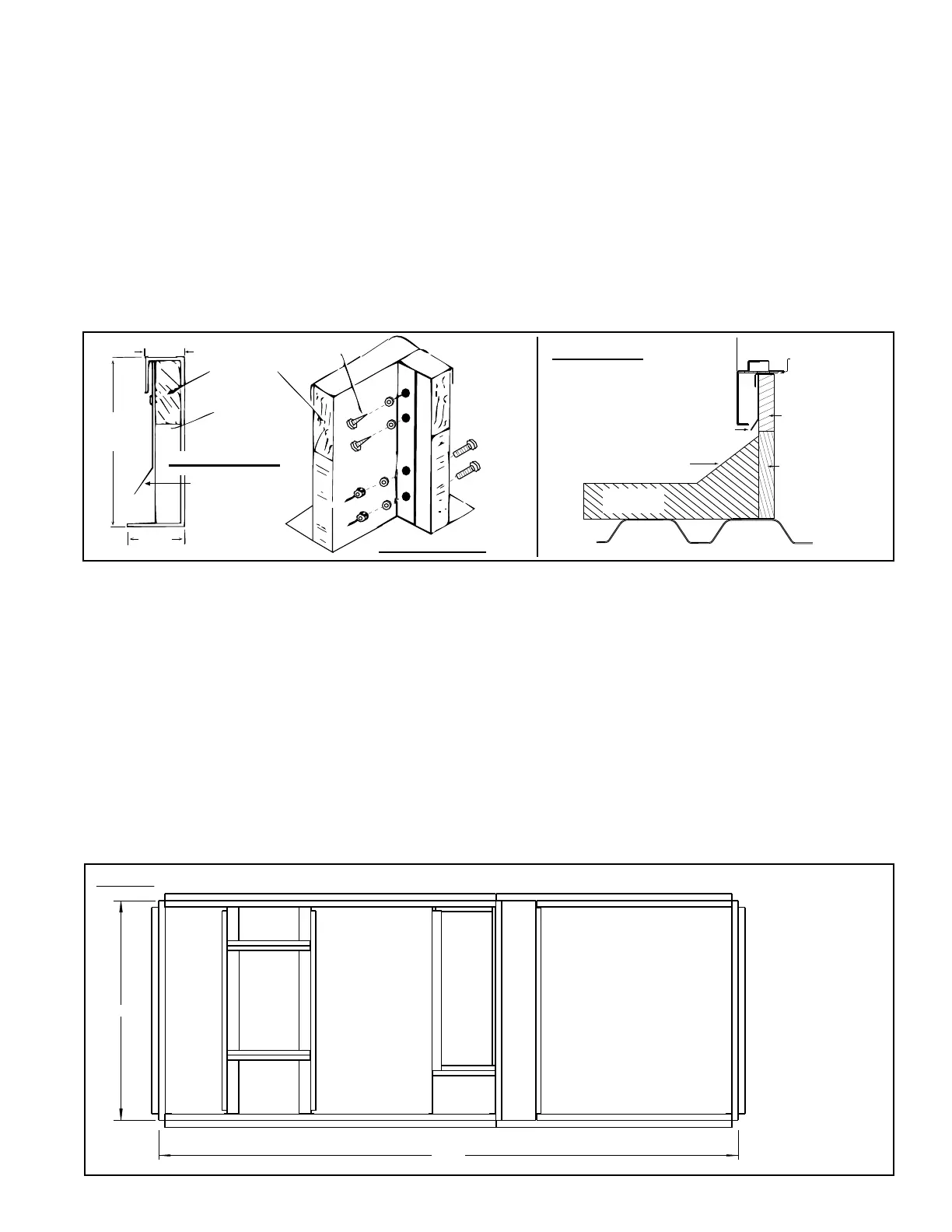
Curb Detail
Corner Detail
Curb Section
FIGURE 8B - Option
CJ34 Downow Roof
Curb Cross Section and
Corner Detail
MUST be sealed
between curb cap
and top of curb
Cabinet
2x4 Wood Nailer
Counter Flashing
(by installer)
Cant Strip
(by installer)
Weld, bolt, or lag screw curb to deck structure.
Roofing Felts
(by others)
Insulation
2. Assemble the Energy Recovery Curb Section
a) Position the sides (Codes L and M) as shown in the drawing in FIGURE 8A.
Attach the sides to the assembled curb section with sheetmetal screws.
b) Attach the curb end (Code A). Fasten with bolts and lag screws as illustrated in
the corner detail (FIGURE 8B) .
c) Position the tunnel (Code K) over the opening in the center. Attach with
sheetmetal screws.
3. Check the roof curb for squareness. The curb must be adjusted so that the
diagonal measurements are equal within a tolerance of ±1/8” (±3mm).
4. Level the roof curb. To ensure a good weatherproof seal between the unit curb cap
and the roof curb, the roof curb must be leveled in both directions with no twist end
to end. Shim as required and secure curb to the roof deck before installing ashing
(See Curb Detail in FIGURE 8B).
5. Install eld-supplied ashing.
FIGURE 8C - Curb Dimensions of Option CJ34 for a MAPS
®
unit with
Option ER1
Curb Section for
Energy Recovery
Module
Curb Section for MAPS® Unit (Cabinet A, B, or C)
Supply Air Duct
Connection Size
Same as CxD on
pages 4 and 5.
Return Air Duct Connection
Size Same as ExF on
pages 4 and 5.
Duct Dimensions for
the MAPS® unit are
the same as without
the Energy Recovery
Module.
See dimensions
A, B, C, D, E, F, H, J,
K, M on pages 4-5.
TOP VIEW - Option CJ34 Roof Curb for MAPS® Cabinet Sizes* A, B, or C with Option ER1, Energy Recovery Module
X
Y
* See pages
71-72 for cross-
reference by
Cabinet &
Model.
Dimensions and
Weights
See Table on
next page
for X and Y
Dimensions.

 Loading...
