Form I-MAPSIII&IV, P/N 222917R9, Page 17
Assembly and
Installation Instructions
for Option CJ49
and CJ50, Curbs for
Horizontal Airow
Counter
Flashing
(by installer;
install after
curb assembly)
Insulation
2 x 4 Wood
Nailer
Cabinet
Cant Strip
(by installer)
Weld, bolt,
or lag screw
curb to deck
structure.
1” Lag Screw and
Lockwasher
(1 per corner)
(4 per corner) 3/4” Hex Head
Cap Screws with Lockwashers
and Hex Nuts
A
B
B
Return
Air
Cap
3 C’s
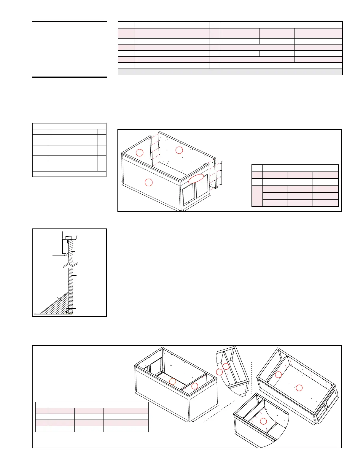
FIGURE 9A - Assemble Curb Ends (A&C) and
Curb Sides (B&B)
3. Check the assembly for squareness. The curb must be adjusted so that the
diagonal measurements are equal within a tolerance of ±1/8” (±3mm).
4. Level the roof curb. To ensure a good weatherproof seal between the unit curb
cap and the roof curb, the roof curb must be leveled in both directions with no twist
end to end. Shim as required and secure curb to roof deck. (NOTE: Install internal
ducts before ashing; see Step 5.)
5. Install solid partition (Code D), duct bottom (Codes E & F), and air bafe (Code
G) using sheetmetal screws (See FIGURE 9C).
a) Position the solid partition (Code D) with insulation side toward the solid end
of the curb. Align the holes (push the insulation out of the way) and attach
partition to curb sides (B & B).
b) Position insulated duct bottom (Code E) with insulation side up in the bottom
of curb. Align the holes (push the insulation out of the way) and attach
partition to curb sides (B & B). Attach the bottom to partition (D).
c) Position the bottom liner (Code F) over the insulation in the bottom of the
curb. Align the holes and attach around the perimeter.
d) Position the air bafe (Code G) against the partition (D). Align the holes and
attach. Align the air bafe with the holes in the bottom liner (F) and attach.
FIGURE 9B -
Curb Detail
CAUTION: Before
installation, recheck to
be sure that the curb
selected matches the
unit ordered. Verify
the dimensions of the
curb received with the
dimensions on page 19.
ID Description (cont'd)
Qty
Component P/N's (cont'd)
L
Divider (upper part) between Supply
and Return Air Ducts
1
261667 261668 261678
M Duct Divider Top Liner
1
261408 261409 261426
N Duct Divider Bottom Liner
1
261405 261424
P Supply Air Duct Large Top (insulated)
1
261664 261665 261676
Q Supply Air Duct Small Top (insulated)
1
261669 261679
Hardware Bag
1
262438 (see content list, left below)
* See Model Size / Cabinet Size Cross Reference on page 2. ** Curb bottom in Cabinet C is 2-piece.
A
B
B
C
D
E
D
F
D
E
A
A
B
B
Install D and E
(See NOTE).
Install F
(See
NOTE).
B
A
D
F
B
G
Install
G.
FIGURE 9C - Install Supply
Duct Partition (D), Bottom
(E), Bottom Liner (F), and Air
Bafe (G)
NOTE: Cabinet C - Insulated bottom
(Code E) and Bottom Liner (Code F)
are two piece.
Insulation NOTE: There is no exposed insulation in the ducts.
All insulation in airow paths is covered with a liner.
1. Follow the Steps and refer to the curb assembly drawings
2. Position curb ends (Codes A & "large" C) and curb side rails (Codes B & B) as
shown in FIGURE 9A. Join the corners as illustrated.
Locate the 4-pc bundle labeled (C). Using sheetmetal screws from the hardware
package, attach the duct ange pieces to both the inlet and return air openings.
If not using return air in the installation, position the return air cap (C) over the
opening and attach. If a return air duct will be used, the cap is not needed.
Assy Hardware Bag, P/N 262438:
P/N Description Qty
1035 Nut 5/16" Hex-18 Thread 16
1333 Lockwasher 5/16 In. 20
16243
Hex Hd Lag Bolt 5/16” x
1-1/4”
4
16247 Cap Screw 5/16 X 3/4" 16
11813
S/M Screw #10-16x1/2
Ab Stalgd
125
66302 1-1/4x1/4 x 50 ft Sealant Tape
ID P/N by Cabinet Size
A A-261653 B-261654 C-261670
B A&B-261655 C-261671
C
A-261656 B-261657 C-261672
A-
261386
B-261387 C-261414
A-261388 B-261389 C-261415
ID P/N by Cabinet Size
D A-261658 B-261659 C-261673
E A-261660 B-261661 C-261674 & 261428
F A-261394 B-261395 C-261418 & 261429
G A-268604 B-268605 C-268606

 Loading...
