Form I-MAPSIII&IV, Page 18
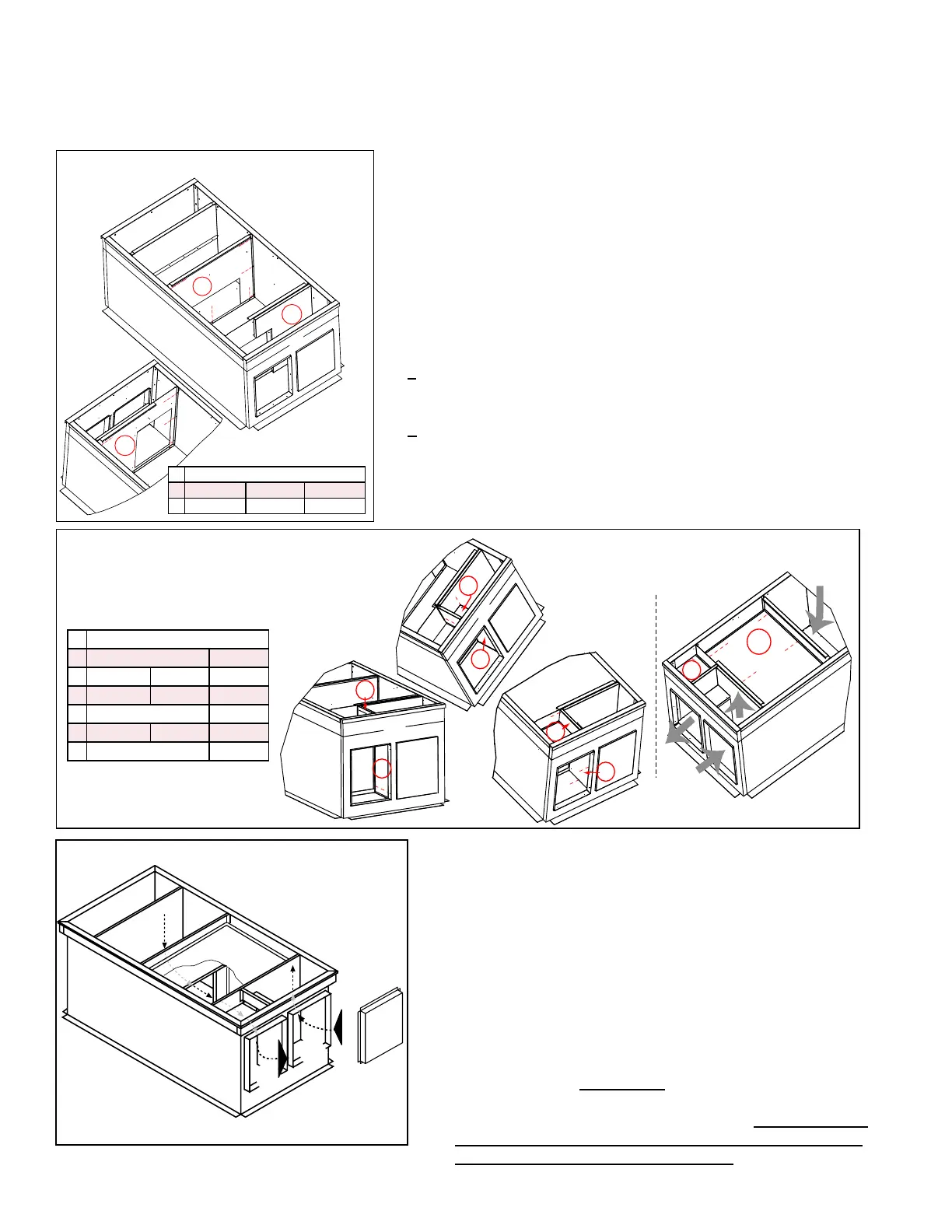
6. Install supply air duct partition (Code H) and return air duct
partition (Code J) using sheetmetal screws. (See FIGURE 9D).
a) Position partition (Code H) in the orientation illustrated. Align
the holes and attach the partition to curb sides (B & B) and
bottom liner (F).
b) Position partition (Code J) in the orientation illustrated. Align
the holes and attach the partition to curb sides (B & B) and
bottom liner (F).
7. Install supply air and return duct dividers (Code K) and (Code L);
divider liners (Code M) and (Code N); and duct tops (Code P)
and (Code Q) using sheetmetal screws. (See FIGURE 9E).
a) Position and attach duct dividers (Codes K & L) as illustrated.
Cover the insulation with liners (Codes M & N) and attach with
screws.
b) Position tops (Codes P & Q) with insulation side up. Align
the holes (push the insulation out of the way) and attach the
perimeter.
8. Install eld-supplied ashing (FIGURE 9B, page 17).
FIGURE 9D - Install the Large Duct
Partitions (H&J)
B
M
N
P
Q
K
L
B
L
K
C
C
And
corresponding
liners (M & N).
Install duct
tops (P & Q).
(insulation
side)
B
B
Install
insulated
dividers
(K & L)
FIGURE 9E - Install Smaller
Duct Partitions and Liners
(K, L, M, N) and Duct Tops
(P&Q)
9. Before placing the MAPS
®
unit or optional duct furnace
on the curb:
□ Apply 1/4" x 1-1/4" foam sealant tape to both the top
surface of the curb rails and the top surface of the perimeter
of the duct dividers, being sure to make good butt joints at
all corners.
□ If installing an optional duct furnace curb section (Option
JH), place it on the curb before the unit. See Paragraph
5.4.3.
□ When it is time to lift the MAPS
®
unit or optional duct
furnace onto the prepared curb (See Rigging and Lifting,
Paragraph 5.5.), be sure that all of the above preparations
have been made. MPORTANT: Verify that the unit will be
placed in the correct airow orientation to mate properly
with the discharge and return air openings. Remember that
the INLET AIR END OF THE UNIT is at the DISCHARGE
(duct connection) END OF THE CURB.
5.4 Mounting on a Roof Curb (cont'd)
5.0 Mounting
(cont'd)
5.4.2 Roof Curbs for Horizontal Airow - Cabinets A, B, C (cont'd)
5.4.2.1 Horizontal Airow Roof Curb Options CJ49 and CJ50 (cont'd)
Assembly and Installation Instructions (cont'd)
ID P/N by Cabinet Size
H A-261396 B-261397 C-261419
J A-261662 B-261663 C-261675
ID P/N by Cabinet Size
K A&B-261666 C-261677
L A-261667 B-261668 C-261678
M A-261408 B-261409 C-261426
N A&B-261405 C-261424
P A-261664 B-261665 C-261676
Q A&B-261669 C-261679
FIGURE 9F - Airow through the Curb

 Loading...
