Form I-MAPSIII&IV, P/N 222917R9, Page 19
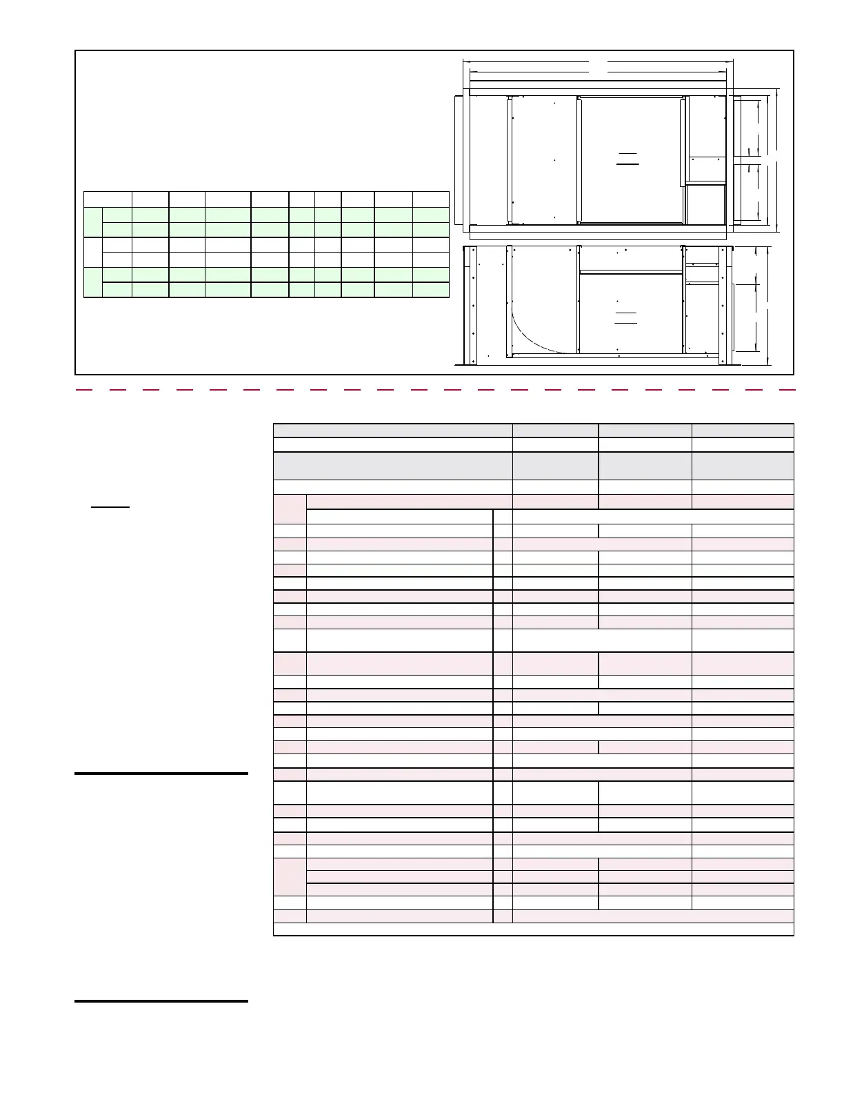
FIGURE 9G - Dimensions and Weights
- Options CJ49 and CJ50 for MAPS
®
Cabinets A, B, and C without an Energy
Recovery Module
Dimensions and Weight
R
S
T
U
V
W
X
Y
TOP
VIEW
SIDE
VIEW
Supply
Duct
Supply
Duct
Return Air
Duct
R
10-3/16
(259)
5.4.2.2 Roof Curbs
for Horizontal Airow
(Options CJ54 and
CJ53) for MAPS
®
III&IV
Cabinets A, B, and
C WITH an Energy
Recovery Module
Components and Application
*See Model Size / Cabinet Size
Cross Reference on pages
71-72.
Cabinet R S T U V W X Y Wt
A*
inches
15 2-5/16
34-13
/16 38-5/8 18 32 69 72-3/4 353 lbs
mm
381 59 884 981 457 813 1753 1848 160 kg
B*
inches
22-1/2 2-5/16
49-13
/16 53-5/8 18 32 69 72-3/4 434 lbs
mm
572 59 1265 1362 457 813 1753 1848 197 kg
C*
inches
28-1/4 2-5/8 61-5/16 65-1/8 22 36 97-7/8 101-5/8 654 lbs
mm
718 67 1557 1654 559 914 2486 2581 297 kg
*See Model Size / Cabinet Size Cross Reference on pages 71-72.
NOTE: Curbs in this section
do not apply to a MAPS
®
unit without an optional
energy recovery module.
For a horizontal airow curb
for a MAPS
®
unit without an
energy recovery module),
go to Paragraph 5.4.2.1,
page 16.
CAUTION: Before
installation, recheck
to be sure that the
correct curb has been
ordered. Be sure that
the curb selected
matches the unit
ordered. Verify the
dimensions of the
curb received with the
dimension table on
page 22.
Roof Curb P/N's by Model & Cabinet Size *
Cabinet A
Cabinet B Cabinet C
Models RCB/RCC/RDB/RDC
*All Sizes *All Sizes *All Sizes
Models RDCB/RDCC/RDDB/RDDC with
Cabinet & Gas Heat Size Combination
With Gas Heat
Sizes 100/150/200
With Gas Heat
Sizes 250/300
With Gas Heat Sizes
400/500/600/700/1000
Models RECB/RECC/REDB/REDC
*All Sizes *All Sizes *All Sizes
ID on
Part
Roof Curb Package P/N (Option)
262533 (CJ54) 262534 (CJ54) 262535 (CJ53)
Component Description: Qty Component P/N's
A
Curb End Assembly (solid w/insulation) 1 261653 261654 261670
B
Curb Side Assembly (insulated) 2 261655 261671
C
Supply Duct End (solid insulated partition) 1 261658 261659 261673
D
Supply Duct Bottom (insulated) (** 2 pcs) **1 261660 261661 ** 261674 & 261428
E
Supply Air Duct Bottom Liner (** 2 pcs) **1 261394 261395 ** 261418 & 261429
F
Air Bafe ("curve" in the supply duct) 1 268604 268605 268606
G1
Supply Air Duct Center Divider 1 261396 261663 261419
G2
Return Air Duct Partition Assembly 1 261662 261663 261675
H
Vertical Divider (lower part) between
Supply and Return Air Ducts
1 261666 261677
J
Divider (upper part) between Supply and
Return Air Ducts
1 261667 261668 261678
K
Duct Divider Top Liner 1 261408 261409 261426
L
Duct Divider Bottom Liner 1 261405 261424
M
Supply Air Duct Large Top (insulated) 1 261664 261665 261676
N
Supply Air Duct Small Top (insulated) 1 261669 261679
P
Horizontal Curb End Connector to ER 1 261384 262425
Q
Liner Support 2 262538 262547 262428
R
Right Curb Side Assy (under ER Module) 1 262537 262427
S
Left Curb Side Assy (under ER Module) 1 262536 262426
T
Duct Bottom Assembly (insulated) (under
ER Module) (** 2 pieces)
**1 262539 ** 262548 & 262553 ** 261674 & 262429
U
Curb Tunnel (between unit & ER) 1 261993 261994 260856
V
Bottom Duct Liner (under ER) (** 2 pcs) **1 262541 262550 ** 261418 & 262430
W
Vertical Duct Divider (insulated) 1 262543 262431
X
Vertical Return Air Duct Liner 1 262544 262432
3 Y's
Curb End Assembly (insulated)
1
261656 261657 261672
Duct Flanges (4pcs in one bundle)
4
261386 261387 261414
Return Air Cap (not used with return air)
1
261388 261389 261415
Z
Duct Top Assembly (insulated) 1 262545 ** 262552 & 262556 ** 261676 & 262435
Hardware Bag 1 (see content list, page 11)
*See Model Size / Cabinet Size Cross Reference on page 2. ** Curb part is two-piece; one of each P/N is required.
Assembly and Installation Instructions for Option CJ54 and CJ53, Curbs
with Energy Recovery Module
1. Follow the Steps and refer to the curb assembly drawings
2. Position curb end (Code A) and curb side rails (Codes B & B) as shown in
FIGURE 10A. Join the two corners as illustrated.

 Loading...
