Form I-MAPSIII&IV, Page 20
Assembly and Installation Instructions for Option CJ54 & CJ53, Curbs
with Energy Recovery Module (cont'd)
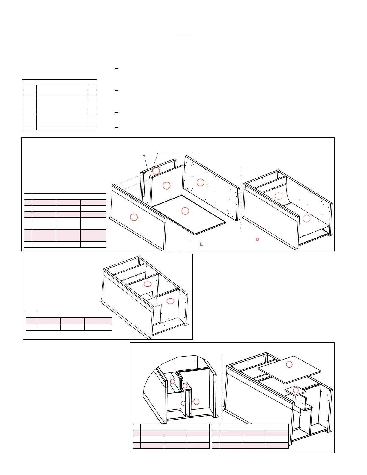
FIGURE 10A - Assemble Curb End (A), Curb Sides (B&B), Supply Duct End (C), Insulated Bottom
(D) Bottom Liner (E)
and Bafe (F)
FIGURE 10B - Install
Duct Partitions G1
and G2
Insulation NOTE: There is no
exposed insulation in the ducts.
All insulation in airow paths is
covered with a liner.
FIGURE 10C - Install Smaller Duct Partitions, Liners, and Tops
5.0 Mounting
(cont'd)
5.4.2.2 Roof Curbs for Horizontal Airow (Options CJ54 & CJ53) for
Cabinets A, B, and C WITH an Energy Recovery Module (cont'd)
5.4.2 Roof Curbs for
Horizontal Airow
- Cabinets A, B, C
(cont'd)
A
B
B
C
D
E
B
B
D
A
C
(8 per corner) 3/4” Hex Head Cap Screws
with Lockwashers and Hex Nuts
2” Lag Screw
& Lockwasher
(1 per corner)
NOTE: Cabinet C - insulated bottom (D) and
liner (E) are both two pieces.
(insulation up)
(liner)
F
4. Install supply air duct partition (Code G1) and
return air duct partition (Code G2) with sheet-
metal screws (FIGURE 10B).
a) Position partition (Code G1) in the orientation
illustrated. Align the holes and attach the
partition to curb sides (B & B) and bottom liner
(E).
b) Position partition (Code G2) in the orientation
illustrated. Align the holes and attach the
partition to curb sides (B & B) and bottom liner
(E).
K
J
H
L
B
B
G2
E
G1
M
N
(Insulation
side up)
B
G2
B
L
E
A
C
G1
K
F
5. Install supply air and return air
insulated duct dividers (Codes H
& J) ; divider liners (Codes K & L);
and duct tops (Codes M & N) using
sheetmetal screws (FIGURE 10C).
a) Position and attach duct dividers
(Codes H & J) as illustrated.
Cover the insulation with liners
(Codes K & L) and attach with
screws.
b) Position tops (Codes M & N)
with insulation side up. Align
the holes (push the insulation
out of the way) and attach the
perimeter.
Hardware Bag includes:
P/N Description Qty
1035 Nut 5/16" Hex-18 Thread 48
1333 Lockwasher 5/16 In. 60
16243
Hex Hd Lag Bolt 5/16" x
1-1/4"
12
16247 Cap Screw 5/16 x 3/4" 48
11813
S/M Screw #10-16x1/2 Ab
Stalgd
210
66302 1-1/4 x 1/4 x 50 ft Sealant Tape
ID P/N by Cabinet Size
A A-261653 B-261654 C-261670
B A&B-261655 C-261671
C A-261658 B-261659 C-261673
D A-261660 B-261661
C-261674
& 261428
E A-261394 B-261395
C-261418
& 261429
F A-268604 B-268605 C-268606
ID P/N by Cabinet Size
G1 A-261396 B-261663 C-261419
G2 A-261662 B-261663 C-261675
ID P/N by Cabinet Size
H A&B - 261666 C-261677
J A-261667 B-261668 C-261678
K A-261408 B-261409 C-261426
ID P/N by Cabinet Size
L A&B-261405 C-261424
M A-261664 B-261665 C-261676
N A&B-261669 C-261679
3. Install supply duct end (Code C) and bottom (Codes D & E).
a) Position the solid partition (Code C) with insulation side toward the solid end of
the curb. Align the holes (push the insulation out of the way) and attach partition
to curb sides (B & B).
b) Position the duct bottom (Code D) in the curb with insulation side up. Align the
holes (push the insulation out of the way) and attach partition to curb sides (B &
B). Attach the bottom (Code D) to the partition (C).
c) Position the bottom liner (Code E) over the insulation in the bottom of the curb.
Align the holes and attach around the perimeter.
d) Position the air bafe (Code F) against the partition (C). Align the holes and
attach. Align the air bafe with the holes in the bottom liner (E) and attach.

 Loading...
