Form I-MAPSIII&IV, Page 34
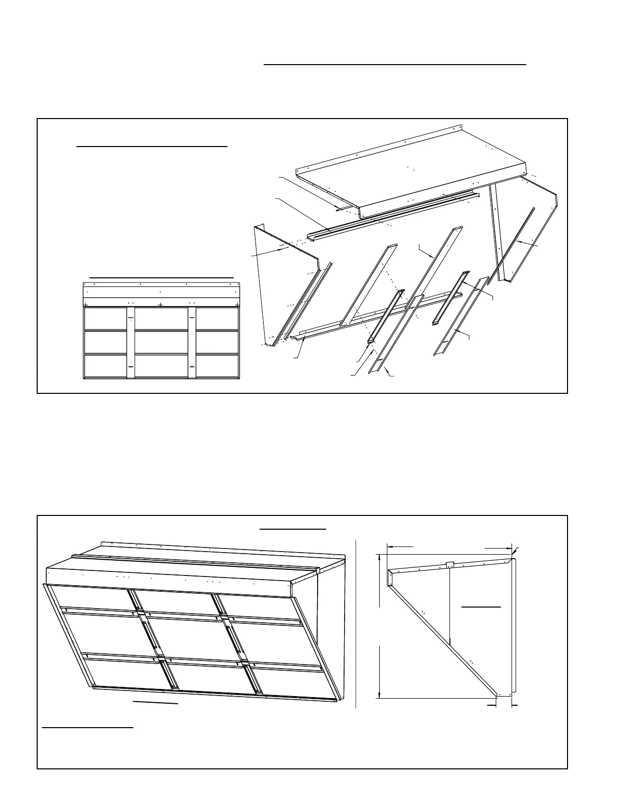
6.3.2 Option AS16,
Inlet Air Hood for
MAPS
®
III "D" Cabinet
Installation Instructions for Inlet Air Hood Option AS16 for D Cabinet
Models
To avoid possible damage, it is recommended that the outside air hood be installed
after the system has been placed on the roof. The air hood should be installed before
the blower is operated. Do not install the hood while the system is in operation. Due to
the size, assembly and installation requires two persons.
6. Mechanical
(cont'd)
6.3 Outside Air
Hood (cont'd)
FIGURE 17D - Installation of Outside Air
Hood, Option AS16 or Option AS19, on
MAPS
®
III Cabinet C Models
For a cross-reference of
cabinet size and model size,
refer to the Appendix,
pages 71-72.)
FIGURE 17D - Cabinet Size C with or without a power exhaust option - Attach
the top lter ller, the two vertical lter supports and the two side lter angles.
Attach the two inner lter spacers with wing screw receptacles. Position the nine
lters in the opening as shown. Secure the lters with the lter clamps and the
wing screws.
6.3.1 Air Hoods for MAPS
®
III A, B, & C Cabinets (cont'd)
Installation NOTES:
- Select screws carefully. Use sheetmetal screws (slotted head with straight tip) when holes in the cabinet are
provided. Use self-drilling screws (head is not slotted with drill-type tip) when matching holes are not provided.
- Follow STEPS in order.
FIGURE 18A - Assembled Inlet Air Hood, Option AS16 for MAPS
®
III D Cabinet
48-11/32” (1228mm)
54-1/4”
(1378mm)
6-1/4” (159mm)
Dimension
from top of
unit and
rear panel.
Side View
of Installed
Hood
(2) P/N 104102,
16x16x1
(2) P/N 104102,
16x16x1
(2) P/N 104102,
16x16x1
(2) P/N 104102,
16x16x1
(2) P/N 104102,
16x16x1
(2) P/N 104102,
16x16x1
(2) P/N 101609,
16x25x1
(2) P/N 101609,
16x25x1
(2) P/N 101609,
16x25x1
Inlet View of Installed Hood

 Loading...
