Form CP-MAPSIII-D21, Doc No 303070, Page 22
Adjusting the unit fan speed to achieve the desired
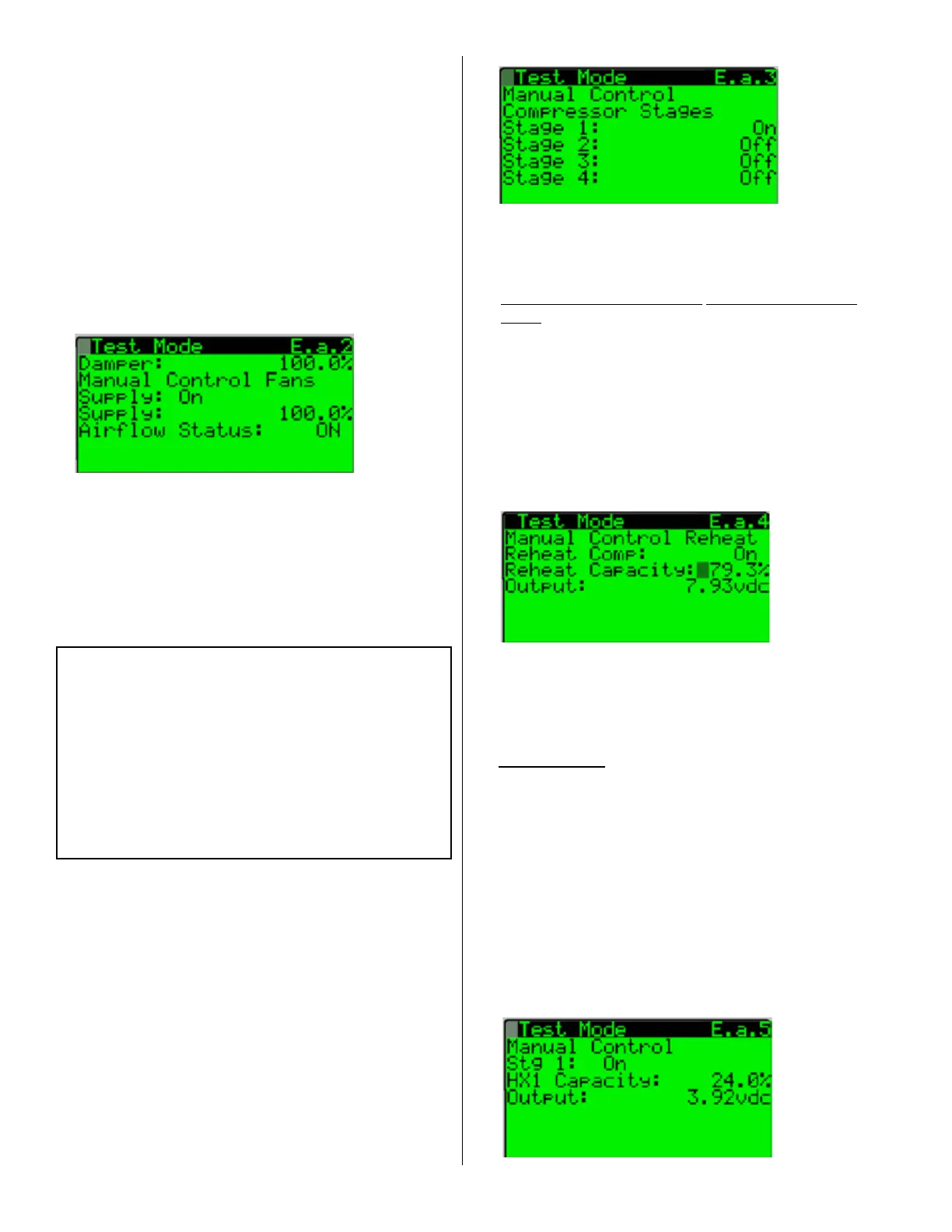
airow volume is accomplished on test mode screen
E.a.2. Reference an auxiliary air measuring device for
setting the maximum fan speeds. If an adjustment is
required use the Supply:%modiableeldandtheup
and down keys to increase or decrease the commanded
fanspeeduntilthedesiredairowvolumeisachieved.
If an adjustment is required, the adjusted value will need
to be saved in the TAB Menu. Instructions for saving set
point values are in Step 15 at the end of the Test Mode
description instructions.
Press the enter key in succession until the cursor
isashingintheuppermostlefthandcornerofthe
screen and use the down arrow key to navigate to the
next Test Mode Screen E.a.3.
11. From the Test Mode Screen E.a.3, press the enter
keyuntilthecursorisashingontheStage 1:
eld.PresstheuparrowkeytosettheStage1
valuetoOn.Verifytherststagecompressorand
associated condensor fan for operation. Repeat
thisstepforstages2through4.Onceveried,
turn all compressor stage values off.
8. Visibly check for proper rotation of the unit supply fan.
If the fan rotation is incorrect, the main unit electrical
supply must be de-energized. Once de-energized, the
electrical phasing will need to be switched at the main
unit disconnect. After the unit phasing is corrected,
re-verify the unit supply fan rotation.
With proper supply fan rotation, close the supply fan
access door, and resume the test mode at Step 9.
9. From the Test Mode Screen E.a.2, verify that the
Supply Fan Airow Status: is reading ON.
NOTE:Proofofsupplyfanairowisrequiredinorder
to complete the Test Mode.
10. Instructions for Setting Supply Fan to Test
and Balance Airow
(Note: Applies to Options VFD1, VFD2 or
VFD3 Only)
Press the enter key in succession until the cursor
isashingintheuppermostlefthandcornerofthe
screen and use the down arrow key to navigate to
the next Test Mode Screen.
12. If the unit is equipped with an optional reheat pump
circuit, from Test Mode Screen E.a.4, press the
enterkeyuntilthecursorisashingontheReheat
Comp:eld.Presstheuparrowkeytosetthe
Reheat Comp: value to On. Press the Enter Key
untilthecursorisashingontheReheat Capacity:
eldandusetheUpArrowKeytosetthecapacity
to 100%. Verify that the Reheat Compressor is
operating and that the refrigerant gas is now
being diverted into the indoor condensor reheat
coil.OnceveriedsettheReheat Comp: value
to Off and the Reheat Capacity: value to 0%.
Press the enter key in succession until the cursor
isashingintheuppermostlefthandcornerofthe
screen and use the down arrow key to navigate to the
next Test Mode Screen E.a.5.
13. Gas Heat Only-Theunitiscongurablewith
up to two modulating gas heat sections. The
modulating gas valve(s) and their associated heat
capacity value will need to be used to verify and (if
required) adjust the manifold pressure settings. See
Installation manual for manifold pressure adjustment
instructions.Toteststagedameproving,seethe
following instructions.
From the Test Mode Screen E.a.5, press the enter
keyuntilthecursorisashingontheHX1 Capacity:
eldandpresstheuparrowkeytosettheHX1
Capacity: value to 24%. Press the enter key until the
cursorisashingontheStg 1:eld.Presstheup
arrow to set the Stg 1 value to ON.
5.0 Start Up (Cont’d)
5.3 Unit Test Mode (Cont’d)