1701ULSA(EC)--EN, p. 11/30
6INSTALLING
WARNING
Checkthesupportingstructuretoverifythatithassufficientload‐carryingcapacityto
supporttheunitweight.
Suspendtheheateronlyfromthethreadednutinserts.Donotsuspendfromtheheater
cabinetpanels.
Donotplaceoraddadditionalweighttothesuspendedheater.
Thelocationwheretheairheateristobeinstalledmustprovidesufficientspacearoundtheheaterfor
servicingandclearancesforsafety(seefigure2).
Whentheunitisliftedforsuspension,leavetheunitonthepallet.Beforehangingverifythatallscrews
originallyusedto
fixtheshippingsupportsarere‐screwedintothecabinet.
Ensurethattheheaterisinstalledinalevelplaneandvibrationfree.
Theairheatermustbefastenedsecurelytoanybasemountingarrangement.
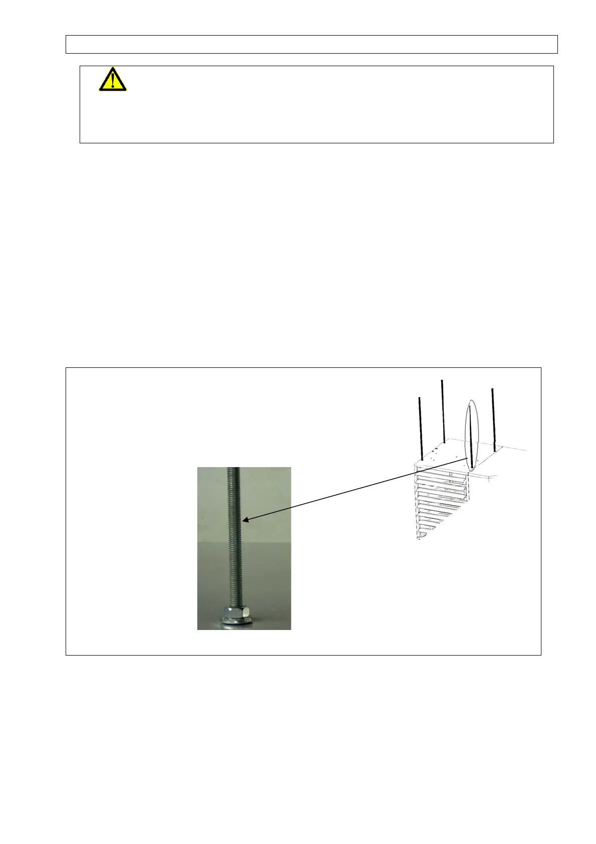
Theheaterissuppliedwithfourpointsuspension.Allpointsmustbeused.
Threadednutinsertsareprovided
oneachsideofthetopoftheheater.Seefigure4.
Aftersuspensiontheairheatershouldberigidsoastoavoidplacingastrainonthefluesystem,gasservices,
electricalwiringandductwork.1”BSPmountingcapnutsare
optional.
IncaseofatypeCinstallation,thedistancebetweenthefloorandtheundersideoftheairheatermustbeat
least1.70m.Combustionairshouldbetakenfromaheightthatexceedstheabovementionedheightof
1.70m.Alsothermostatsandswitcheswhicharenotsparklesshave
tobeinstalledataminimumheightof
1.70m.
Figure4
Besurethatthethreadedhangerrodsarelockedtotheheaterasillustrated
in this figure. Recommended maximum hanger rod length is 1.8m. Where
longerdropsarerequired,ensurethatrestraintsarefittedtopreventexcess
lateralmovementand supportsareadequatelysized. Alternativelytheunit
canalsoebase
mountedonanon‐combustiblesupport.Inthiscaseensure
thatunitissecurelyfixedonthebase.