1701ULSA(EC)--EN, p. 17/30
9GASSUPPLY
GASCONNECTION
Werefertotable1ofsection3forallgasspecifications
WARNING
Connectiontoagasserviceinstallationmayonlybecarriedoutbysuitablyqualifiedpersons.
Thegasinstallationmustcomplywithallrulesinforce.
Onlymaterialsappropriateforgasserviceinstallationmaybeused.
Donotrelyontheheatertosupportthegaspipe.
NEVERUSEAFLAMETOTESTFORGASSOUNDNESS.ALLCOMPONENTSOFAGASSUPPLY
SYSTEMMUSTBELEAKTESTEDPRIORTOPLACINGEQUIPMENTINSERVICE.FAILURETO
COMPLYCOULDRESULTINPERSONALINJURY,PROPERTYDAMAGEORDEATH!
9.1GENERAL
ULSA/ULSAECheatersaredesignedtooperateoneithernaturalgas(G20),propane(G31)orbutane(G30)gas.Check
thatgassupply,gascategory&gasinletpressureisinaccordancewiththedatadescribedontheairheater.Toletthe
unitfunctionatmaximalheatoutput,thegas
supplypipeMUSTbecorrectlysized.Closetotheairheateragastapwith
couplingmustbemountedforservicing(seefigure11).Itisstronglyrecommendedtoplaceagasfilterandcleanthe
gastubewithnitrogen.
Thewholeofthegasserviceinstallationincludingthemetermust
beinspected,testedforsoundnessandpurgedin
accordancewithappropriaterequirementsbyaqualifiedperson.
9.2GASCONNECTION
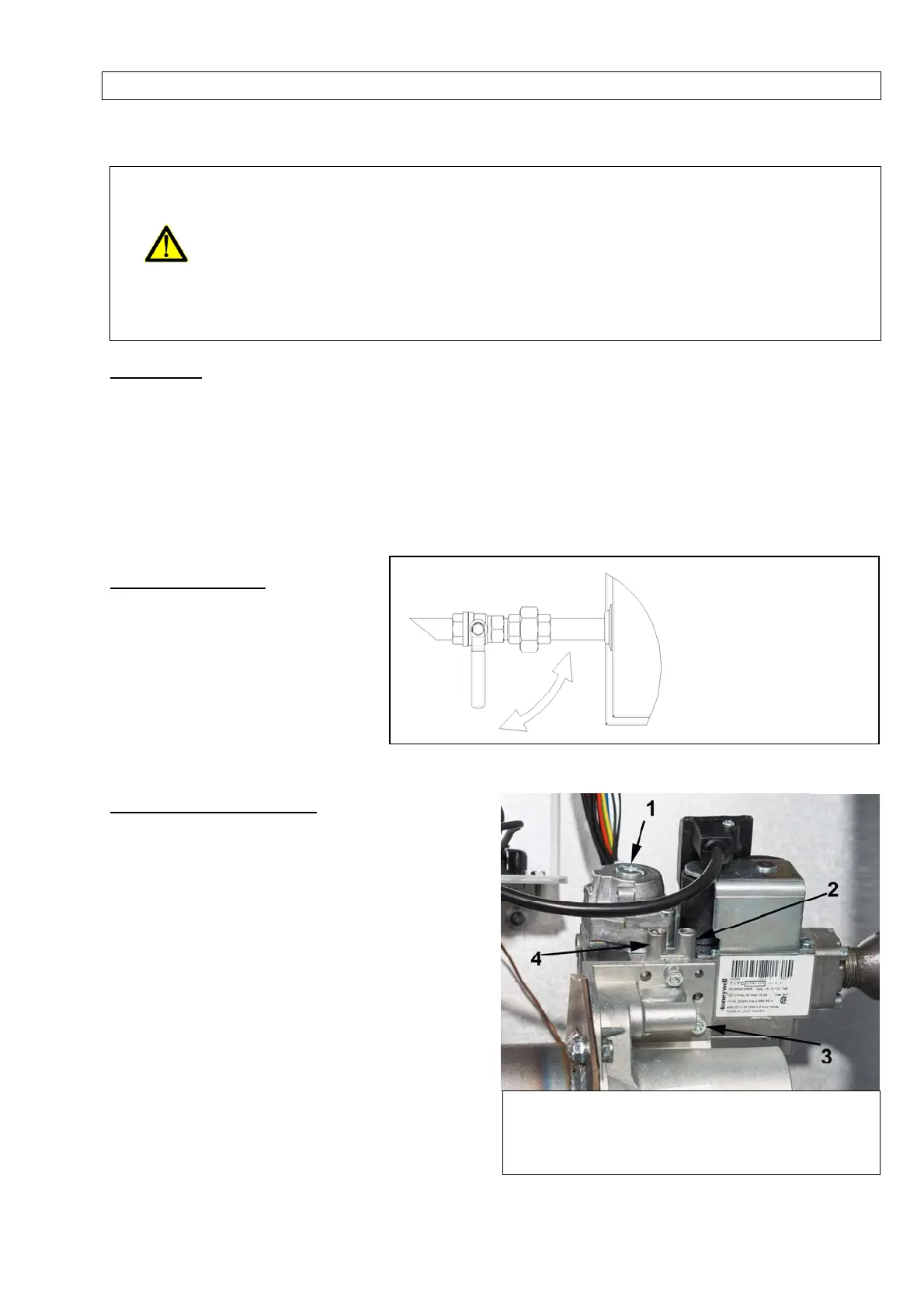
9.3ADJUSTMENTGASVALVE
Toadjusttheoffset,removetheprotectionscrewon
thetopandregulatetheoffsetbyusingtheexposed
screw.Offsetvalueswillbemeasuredintheindicated
points.
ToadjusttheCO
2
,useascrewdriverintheindicated
spotandturnthescrewdriverclockwisetodecrease
themeasuredCO
2
orturnitcounterclockwiseto
increasethemeasuredCO
2
.TheCO
2
measurement
shouldbedoneinthefluedischargepipe.
A
llunitsaresetaccordingtothedataplatebefore
leavingthefactory.Anymodificationtothegasvalve
mustbedonebyaqualifiedtechnician.
1 Offsetadjustmentpoint
2 Inletpressuremeasuringpoint
3 CO
2
adjustmentpoint(throttle)
4
Offsetmeasuringpoint
REMARK:
Donotovertighten
anddonotrotatethe
gasvalveinsidethe
heatercontrol
com
artmen
Figure12
Figure11