1701ULSA(EC)--EN, p. 27/30
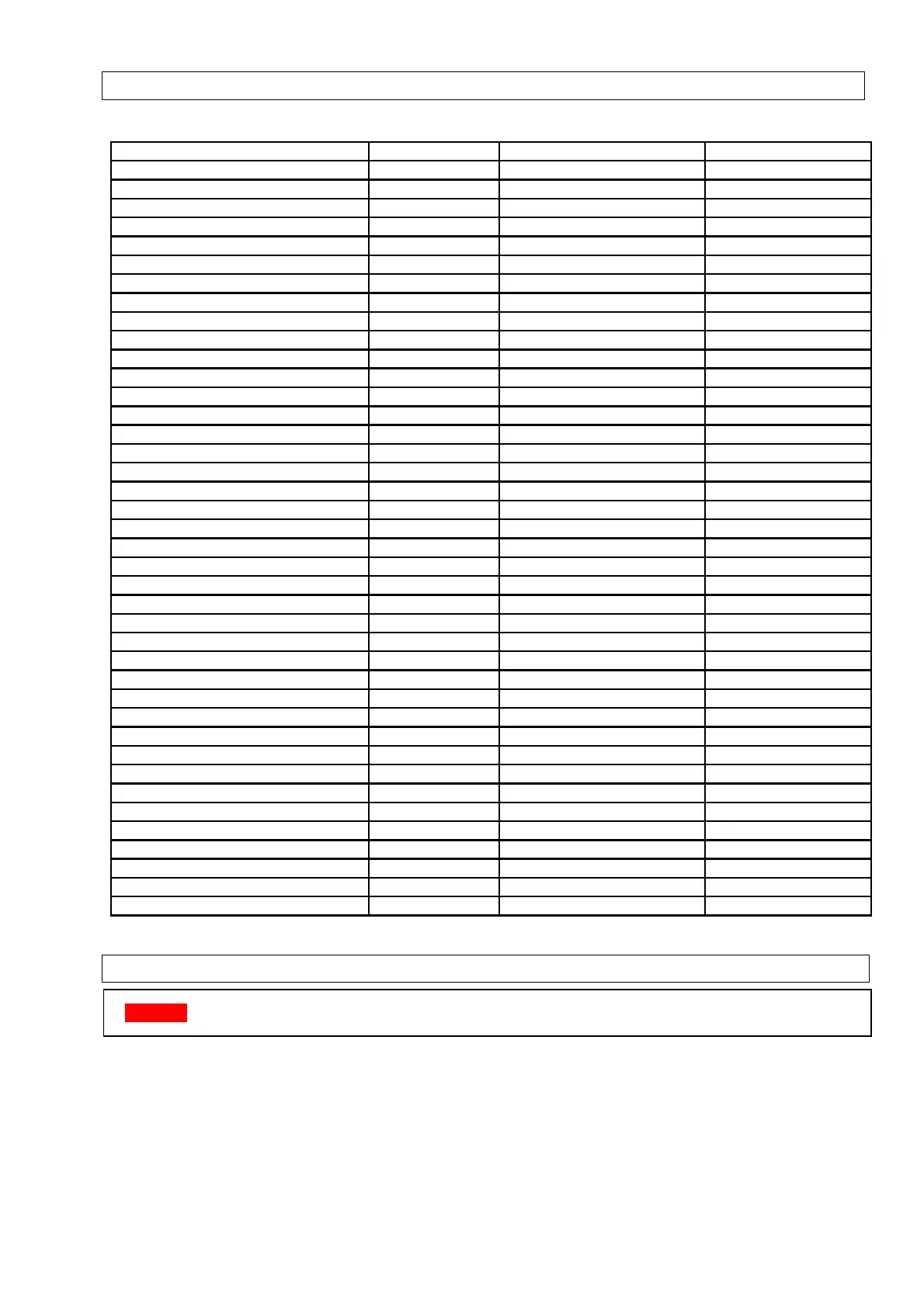
14.PARTSLIST
Description Part number Reference Application
motor+ventilator 01 26060 FN040-4EW.0F.A7P1 025 ULSA AC
motor+ventilator 01 26061 FN040-4EW.0F.A7P2 035 ULSA AC
motor+ventilator 01 26040 FN045-4EW.4I.A7P1 050 ULSA AC
motor+ventilator 01 26063 FN063-6EW.4I.A7P1 075 ULSA AC
motor+ventilator 01 26040 (2x) FN045-4EW.4I.A7P1 100 ULSA AC
motor+ventilator 01 26070 S3G400-LK08-H4 025 ULSA EC
motor+ventilator 01 26070 S3G400-LK08-H4 035 ULSA EC
motor+ventilator 01 26071 S3G450‐LL03‐H4 050 ULSA EC
motor+ventilator 01 26072 S3G630‐AE55‐22 075 ULSA EC
motor+ventilator 01 26071 (2 x) S3G450‐LL03‐H4 100 ULSA EC
venter 20 25747 RG148 025-035-050
venter 20 25748 RG175 075-100
burner relay 03 25327 TC340 all
interface burner relay 03 25327 01 344 all
main cable tree 06 41850 all
limit control LC1 05 25167 5050 T7335B all
limit control LC3 03 24959 542332 all except 075 ULSA EC
limit control LC3 03 24959 03 10H14 075 ULSA EC
flame sensor 05 25171 EXP0048 025
flame sensor 05 25191 PSE-RZ30 035-100
ignition electrode 05 25169 exp0049 025
ignition electrode 05 25190 PSE-RZ29 035-100
reset switch 60 61988 2645 all
signal lamp 60 61997 all
pressostat 30 60621 13 605 all
venturi gas valve 03 25700 003 0 0 3 025
venturi gas valve+40cm tube 03 25700 051 0 51 035
venturi gas valve+20cm tube 03 25700 051 0 51 050
venturi gas valve 03 25700 051 0 51 075
venturi gas valve 03 25700 050 0 50 100
premix gas valve 03 25800 VK4115V 025-075
premix gas valve 03 25801 VK4115VB1012B 100
gas valve plug+wire 03 25141 V1 45900441 all
burner 50 60250 025 51416 025
burner 50 60250 035 51425 035
burner 50 60250 050 51418 050
burner 50 60250 075 51420 075
burner 50 60250 100 51422 100
Coil 30 61742 240V 66.82.8.230.0000 all
Siphon 70 61761 Waven all
15.USERINSTRUCTIONS
Attention
Neverswitchoffelectricitysupplytotheairheaterwithoutfirstclosingthegasisolatingtap.
Howtheairheaterworks:
Gas is burn ed by an atmospheric burner wh ich fire s int o a heat exchanger. The gas burner is
controlled by a double gas valve via an electronic burner control,
which is operated automatically via
external controls i.e. a room thermostat and/or a time switch. The burner is lit by a spark ignite r.
When the burner fires and warms the heat exchanger,the heat issensed by a thermally operated fan
control,whichswitchesonthefanwhentheair
temperaturehasreacheditspresetoper atinglevel.