1701ULSA(EC)--EN, p. 12/30
7AIRSUPPLY&FLUESYSTEM
7.1GENERAL
WARNING
Thefluemustbeinaccordancewithallinternationalandnationalrulesandregulationsin
force.Localrequirementsmayapplyinadditiontonationalrequirements.
Failuretoprovideproperflueingcouldresultindeath,seriousinjuryand/orproperty
damage.
Theproductsofcombustionmustbefluedtooutside
atmosphere.Commonflues(formore
thanoneappliance)mustnotbeused.
Singlewallfluepipeexposedtocoldairorrunthroughunheatedareasshouldbeinsulated
toavoidcondensation.
Ifthefluepassesthroughacombustibleelementofthebuildingitmustbeenclosedbya
sleeveofnon‐combustiblematerialandseparatedfromthesleevebyatleasta25mmair
break.Thetemperatureofanycombustiblematerialneartothefluemustnotexceed65°C
whentheheaterisinoperation.Thefluemustbeatleast50mmawayfromany
combustiblematerial.
Provision
mustbemadeforcondensationtoflowfreelytoapointtowhichitcanbe
released,i.e.drain.
ModelULSA/ULSAECheatersmaybeinstalledastypeBortypeCinstallations.Theunitheatersaredesignedto
operatesafelyandefficientlywitheitherahorizontalorverticalfluesystemwheninstalledaccordingtothe
specificrequirementsandinstructions.Ifthisheaterisreplacinganexistingheater,besure
thattheflueisofthe
correctsizeandthattheexistingflueisingoodcondition.Acorrectlysizedfluesystemisrequiredforsafe
operationoftheheater.Animpropersizedfluesystemcancauseunsafeconditionsand/orcreatecondensation.
Theunitsmaybeinstalledasabalanced
fluetypeCheaterrequiringbothacombustionairinletpipeandaflue
pipeorasapowerventedheatertypeBwherethecombustionairistakenfromthespacewhereheateris
installedandwhichrequiresonlyafluepipeexhaustingtooutdoors.Allproductsofcombustionmust
befluedto
outdooratmosphere.
EachheaterinstalledasatypeBappliancemustbefittedwithanindividualfluepipeandthecombustionairinlet
openingmustbeprovidedwithaprotectiongrill.
EachheaterinstalledasatypeCappliancemustbefittedwithanindividualcombustionair/flue
pipesystem.Type
C2appliance,withsinglepipesystemforsupplyofcombustionairandevacuationoffluegasses,arenotallowed.
Fortesting,thefluepipeshouldincludeasealabletestpoint.Ideallythetestpointshouldbeatleast450mmaway
fromtheairheaterflueconnection socket.However
ifaconcentricflueisattacheddirectlytotheconnection
socketsthenthecombustionshouldbetestedthroughtheflueoutletcollarviaadrilledtestpointwhichmustbe
securelypluggedoncompletion.
Followthefluepipemanufacturer’sinstallationinstructionsformakingjoints,includingconnectionstotheair
heater,
forpassingthroughabuildingelementandforsupportrequirements.
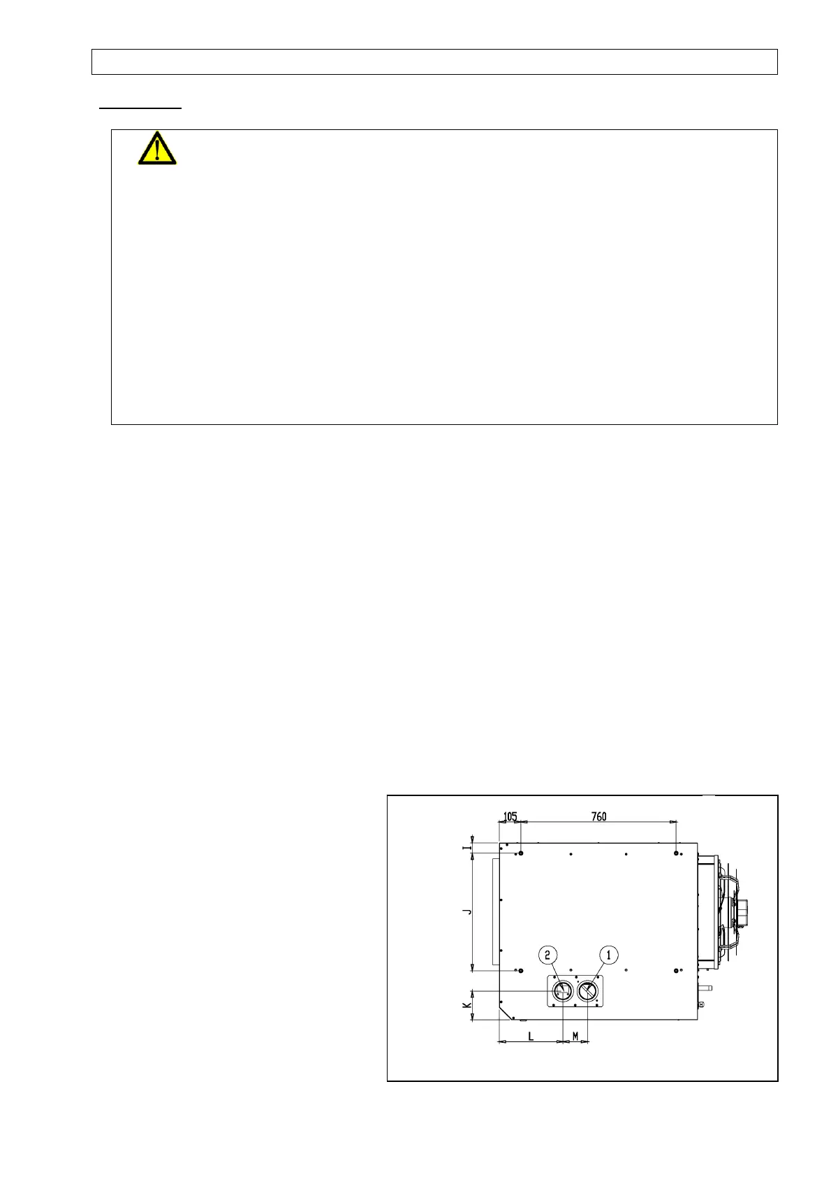
Figure5:
Combustionairandfluepipesockets(standard
version)
Remark:
Acoverplatecanbeinstalledontherearor
toppanel.Theplatewiththefreshairinlet
andtheflueoutletsocketisfactory
installed
onthetoppanelbutcaneasilybereplacedon
therearpanelifrequired.Incaseofchange,a
separatekitmustbeorderedatthesupplier.
Combustionairinlet
Flueconnection