10
Assembly and adjustment instructions RF-KIT Power Amplifier RF2K-S
Step 10: Adjustment voltage display
► Adjust voltage display at the Touch screen (2)
(Menu → Calibration → Poti Config: “Indication area Voltage“)
with R26 on the Controller board to 53,5 V.
Step 11: Test of frequency measurement and lowpass filter circuit
► Set the transmit power of the TRX to 5 W (CW/AM/FM) reading on your
reference wattmeter.
► Connect TRX to Exciter input (17).
► Connect Dummy load to ANT1 (6).
► Operate PTT.
The frequency display of the PA should match that of the control transmit
-
ter +/- 2 kHz.
► Check whether the display of the current band filter also changes on
the Touch screen (2) when the frequency or band is changed and
whether the correct band filter is displayed.
There are control LEDs on the Lowpass Filter Board:
► Check for all bands whether the band filters are also changed when
the frequency or band is changed and whether the correct band filter
is selected (corresponding LED lights up red).
► Release PTT, stop transmitting.
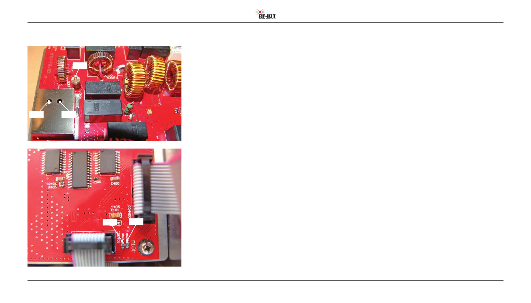
Position of the adjustment elements and measuring points on the
Tunerboard
R515 R502
C500
R526
R525
Adjustment power display
The following power-based adjustments are carried out in the 20 m band
(14 MHz).
Step 12: Adjustment forward power display (low)
► Set the transmit power of the TRX to 5 W (CW/AM/FM) reading on your
reference wattmeter.
► Connect TRX to Exciter input (17).
► Connect Dummy load to ANT1 (6).
► Operate PTT.
► Adjust R502 on the Tunerboard for 1.6 V at measuring point R525.
► Release PTT, stop transmitting.
Step 13: Adjustment forward power display (high)
► Set the transmit power of the TRX to at least 50 W or more (CW/AM/
FM) reading on your reference wattmeter.
► Connect TRX to Exciter input (17).
► Connect Dummy load to ANT1 (6).
► Operate PTT.
► Set R24 on the Controller board so that on the Touch screen (2)
(main screen) the transmit power supplied by the TRX is displayed with
the correct value as forward power.
► Release PTT, stop transmitting.