13
Assembly and adjustment instructions RF-KIT Power Amplifier RF2K-S
Step 19: Severe Error Alarm
► Connect TRX to Exciter input (17).
► Connect Dummy load via Reference wattmeter to ANT1 (6).
► Tune TRX to a frequency in the 20 m band (14 MHz).
► Adjust R19 on the Controller board about 10 turns counterclockwise.
► Switch the device to “Operate“ by tapping switching area Standby.
► Set the transmit power of the TRX to 5 W (CW/AM/FM) reading on your
reference wattmeter.
► Operate PTT.
If a Severe Error Alarm is already triggered now, R19 on the
Controller board must be adjusted further counterclockwi-
se. This will continue until the alarm message disappears.
► Gradually increase the transmit power of the TRX until 500 W is dis-
played on the reference wattmeter (the power display of the PA
display may still show a different value, as it will be calibrated in the
next step).
► Keep PTT pressed.
► Adjust the PAF display with R19 on the Controller board until the
value “1100“ is displayed.
(Menu → Calibration → Poti Config: “Indication area PAF“)
► Release PTT, stop transmitting.
Step 20: Adjustment forward power display (full power)
This adjustment is carried out in the 80 m-Band (3.5 MHz).
► Connect TRX to Exciter input (17).
► Connect Dummy load via Reference wattmeter to ANT1 (6).
► Operate PTT.
► Slowly increase the TRX transmit power from 5 W until Reference
wattmeter reads 1000 W (CW/AM/FM).
► Set R24 on the Controller board so that on the Touch screen (2)
(main screen) Forward power is displayed with 1000 W.
► Release PTT, stop transmitting.
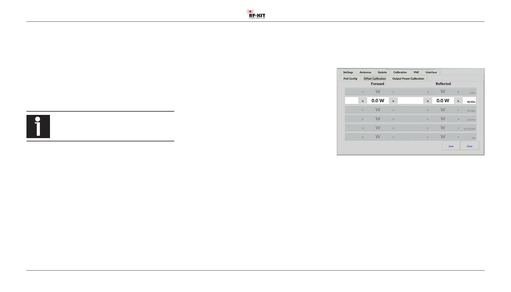
Step 21: Fine adjustment power display via the menu
Please also note the description in the operating instructions
(➔ page 14, “Oset Calibration“)
Go to
Menu → Calibration → Oset Calibration:
The unavoidable frequency-dependent deviations of the linearity of the
directional coupler used for internal power measurement can be minimi-
zed for each bandpass range. The adjustment should be performed at an
output power of 1 kW. Use your preferred reference wattmeter for the ad-
justment.
Selection of the bandpass range is done automatically during transmission.
The detected band is highlighted.
► Adjust the internal power display by tapping switching areas
> (increase value) respectively < (decrease value).
Brief actuation changes the value in the indication area Forward by 0.1 W.
Longer actuation changes the value continuously.
► Press the switching area Save to store the settings.
► Repeat this procedure for each bandpass range to be adjusted.