11
Assembly and adjustment instructions RF-KIT Power Amplifier RF2K-S
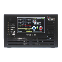
Step 16: Adjustment SWR-measuring bridge
► Switch the device to “Standby“ using the switching area “Standby“.
► Choose the 6 m-Band (50 MHz).
► Set the transmit power of the TRX to 5 W (CW/AM/FM) reading on your
reference wattmeter.
► Connect TRX to Exciter input (17).
► Connect Dummy load to ANT1 (6).
► Operate PTT.
► Adjust C500 on the Tunerboard to display minimum SWR at the
Touch screen (2) (main screen).
Step 14: Adjustment reflected power display (low)
► Set the transmit power of the TRX to 5 W (CW/AM/FM) reading on your
reference wattmeter.
► Connect TRX to ANT 1 (6).
► Connect Dummy load to Exciter input (17).
► Operate PTT.
► Adjust R515 on the Tunerboard for 2.7 V at measuring point R526.
► Release PTT, stop transmitting.
Step 15: Adjustment reflected power display (high)
► Set the transmit power of the TRX to at least 50 W or more (CW/AM/
FM) reading on your reference wattmeter.
► Connect TRX to ANT 1 (6).
► Connect Dummy load to Exciter input (17).
► Operate PTT.
► Set R23 on the Controller board so that on the Touch screen (2)
(main screen) the transmit power supplied by the TRX is displayed with
the correct value as reflected power.
The bargraph of the reflected power on the main screen will deflect full,
but the digital power display will still show the value to be adjusted cor
-
rectly.
► Release PTT, stop transmitting.