12
Assembly and adjustment instructions RF-KIT Power Amplifier RF2K-S
Step 17: Looping in the PA module
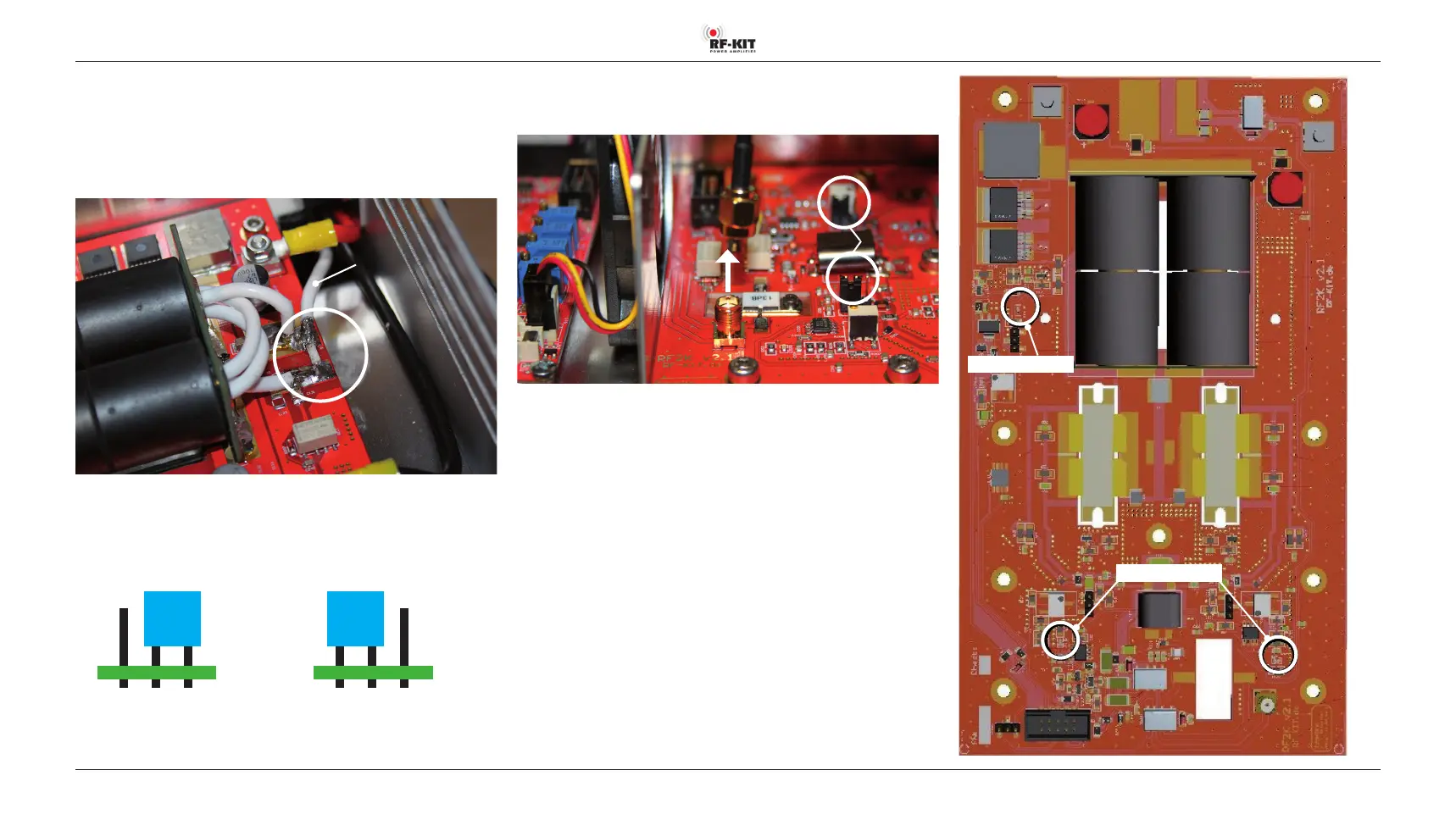
► Disconnect SMA plug “Pigtail“ and unsolder its free end from the
white coaxial cable.
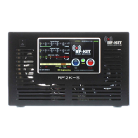
► Solder the free end of the white coaxial cable to the output of the PA
module.
White
coaxial cable
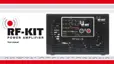
There are 2 bias jumpers on the PA module. On delivery both jumpers are
in position “BIAS OFF“.
► Set both jumpers to position “BIAS ON“.
Delivery status: “BIAS OFF“ Operating status: “BIAS ON“
Rear panel
Rear panel
Step 18: Adjustment display current consumption
► Remove SMA plug from input SMA socket PA module.
“BIAS ON“
► Switch the device to “Operate“ by tapping switching area Standby.
Now LED “53 V-On“ lights up.
► Connect TRX to Exciter input (17).
► Connect Dummy load to ANT1 (6).
► Set the transmit power of the TRX to 5 W (SSB).
► Operate PTT, whistle briefly into the microphone until both Bias-LED
light up green.
► Keep PTT pressed.
► Adjust Quiescent current with R25 on the Controller board until
3.6 A is displayed on the Touch screen (2).
► Release PTT, stop transmitting.
► Plug the SMA plug back into the input SMA socket PA module.
Bias-LED
LED: “53 V-On“
Fig. right: PA module