8
Assembly and adjustment instructions RF-KIT Power Amplifier RF2K-S
Step 9: Preparatory work for alignment
A suitable plug for the Power jack (9) is included in the delivery. With this
plug, together with a suciently dimensioned mains cable and a coun
-
try-specic mains plug, the user has to prepare a mains cable suitable for at
least 16 A current consumption (cable cross-section >1.5 mm
2
).
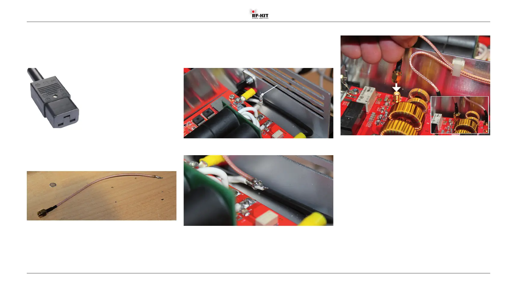
A short piece of coaxial cable with one attached SMA plug (“Pigtail“) is also
included:
► Strip off approx. 15 mm of insulation at the free end of the “Pigtail“ and
tin it.
In the rear area of the power amplifier module, directly in front of the rear
panel, there is the free end of a white coaxial cable.
This coaxial cable normally lies at between the board of the power ampli
-
er module and the rear panel and has been angled upwards for better
visibility in the following picture.
White coaxial cable
with free end
► Solder the “Pigtail“ to the free end of the white coax cable.
► Connect SMA-plug “Pigtail“ to TX/RX-Tuner-module.
Now the power amplier module is bypassed and the control signal is
looped through. All functions of the device can be tested in this way
without generating power.
► Check all plug connections for tight fit, freedom from mechanical
tension and correct connection.
► Connect TRX to Exciter input (17).
► Connect Dummy load to ANT1 (6).
► Establish PTT connection via PTT (7).
► Connect the device to earth via the Ground connector (11) on the
rear panel.
Use a cable with the shortest possible length and the largest possible
cross-section.
► Connect the unit to the mains using the power cable via the Power
jack (9) on the rear panel.