6
Assembly and adjustment instructions RF-KIT Power Amplifier RF2K-S
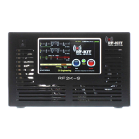
► Place the Raspberry Pi® 4 model B on the spacer bolts as shown in
the picture below and secure it with the 4 screws previously removed
from the spacer bolts.
Step 6: Connection controller board with Raspberry Pi® 4 Model B
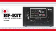
Now the Raspberry Pi® 4 model B must be carefully connected to the
controller board, Touch screen (2) using the 3 cables supplied.
2 cables from the connection sockets at the rear panel for USB and LAN
are also to be connected with the Raspberry Pi® 4 model B.
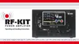
Always take care to avoid any mechanical stress on soldered
sockets of all components.
Especially the HDMI sockets of the Raspberry Pi® 4 Model
B are wellknown to be particularly sensitive in this respect!
► Connect the USB cable already present in the device to
“D lower - USB“ on the Raspberry Pi® 4 Model B.
► Connect the LAN cable already present in the device to
“F - LAN“ on the Raspberry Pi® 4 Model B.
A
B
C
F
E
D
USB from the
rear panel
LAN from the rear panel
Raspberry Pi® 4 Model B:
A - Micro HMDI / B - Micro HMDI / C - Power supply / D, E - 2x USB /
F - LAN
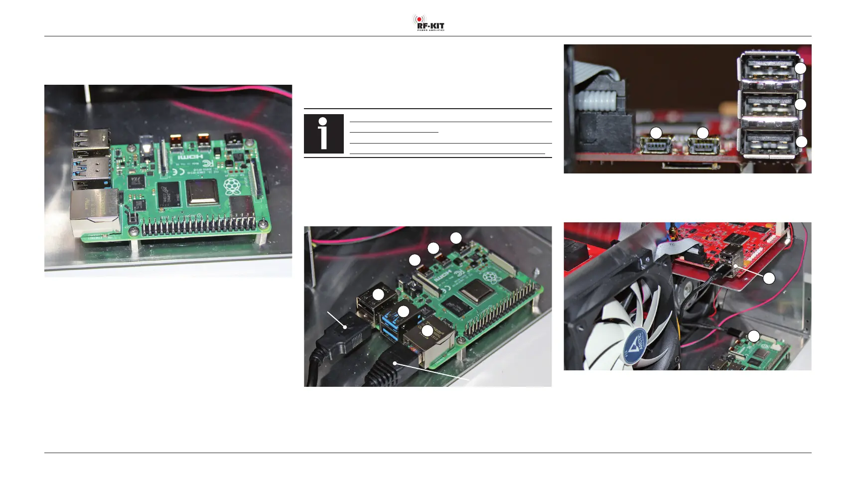
1 2
5
4
3
Controller board: 1 - Mini USB / 2 - Mini USB / 3 - USB / 4 - USB / 5 - USB
► Connect “4 - USB“ on the Controller board to “C - Power supply“
on the Raspberry Pi® 4 Model B.
C
4
► Connect “1 - Mini USB“ on the Controller board to “D upper - USB“
on the Raspberry Pi® 4 Model B.
The socket “2 - Mini USB“ of the Controller board will not be used and
therefore remains free.