13) Drill the larger 1-inch hole using the 1-inch drill bit or hole saw.
Caution: Proceed slowly, 1 layer at a time, verifying after each layer is removed
that no cables or other critical components will be damaged by the hole.
14) Remove the green molex connector (use the small jewelers screwdriver to remove the small
screws) from the Control Cable if you have already installed it to the end of your control cable in
order to pass the cable through the hole. If you haven’t connected it but have spliced it and
striped the wires, you may cut the end off to have a clean edge then pass the control cable
through the hole, resplice and strip the ends again (wires for the control cable should be stripped
back 1/2” from the end and bent back to make a ‘V’ with the cable and then insert into the green
molex connecter) then connect it to the controller and place it in a cabinet. You will also pass the
coax cable(s) 1-3 (depending on your service provider) through the roof entry hole into the
vehicle. Do not pull the cables taut! Leave 2-3 foot of cable on the roof for the next steps.
(Attach the Green 12 Pin Connector in accordance with instructions on the bottom
of the Eagle Controller or figure 2 on pg. 27) If the wires are placed too far into the
connector, it will clamp down on the outer plastic shielding, and will not make
good connection to the wire. Failure to do this correctly will cause your satellite
system to malfunction or cause erratic behavior.
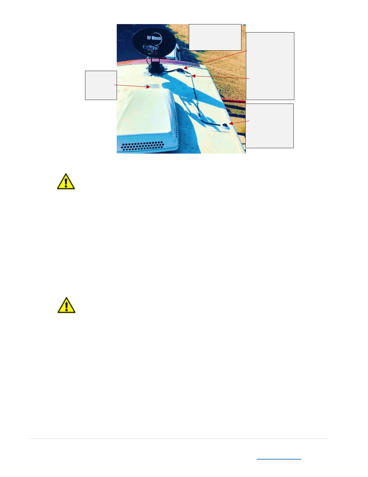
15) Mount the Weather Covered antenna junction box near where the cables connect (within the
‘clearance zone’ near the mount feet) using screws. Use photo at the top of this page as a
reference.
16) Liberally apply Dielectric compound grease to coax cable ends. Connect the controller cable and
coax cables and store the connectors inside the weather cover junction box.