Chapter 1 – Installation
Page 12 of 30 9450 Duolink Exit Alarm Receiver Hardware Installation Guide
0510-1103-G
Location
For optimal location, use the following steps to assess the relative noise in
the environment so that a proper mounting location for the DuoLink may
be chosen. The purpose of this assessment is to make minor adjustments
to the standard mounting configuration in order to achieve an appropriate
location for the DuoLink where its Signal LED indicates minimal activity
with no transmitters in range.
The designed range is 4 feet. The adjustable range surrounding the
antenna location is up to an 8 feet radius, depending on the RF
environment.
NOTE: The following steps are to be performed as a temporary setup.
The final mounting location is not known until the following steps have
been completed.
To determine the location:
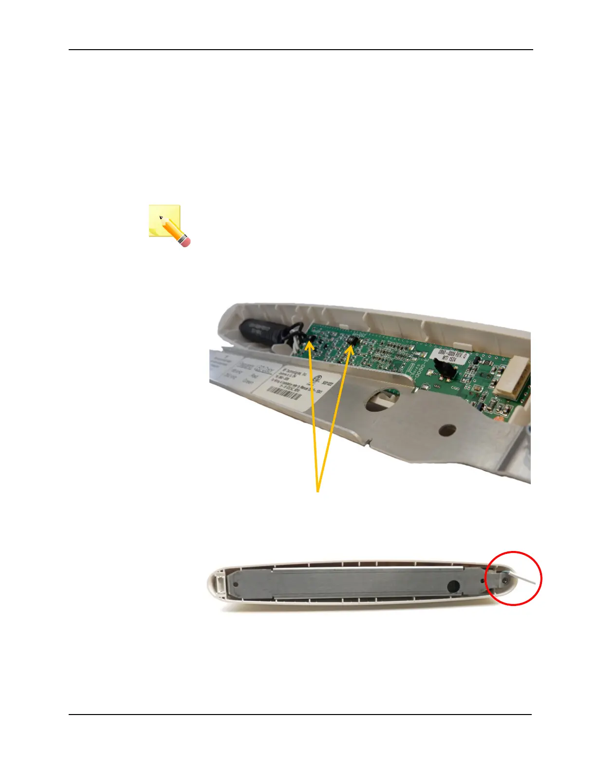
1. Use a 5/64” Allen wrench to remove the metal mounting bracket from
the back of DuoLink
2. Set the frequency switches to match the operating frequency of the
transmitters specified for the facility (66 KHz or 262 KHz). Both
switches (SW1 and SW2) need to be set and in the same direction
3. Terminate the DuoLink to the exit controller as per wiring diagram
(see chapter 2)
4. Replace the metal mounting bracket