Chapter 1 – Installation
Page 20 of 30 9450 Duolink Exit Alarm Receiver Hardware Installation Guide
0510-1103-G
For additional wiring information, refer to the Touchpad Exit Controller
Installation Guide (0510-1100).
WARNING: You must verify that the exit controller is OFF before wiring
any system components. Failing to do this may result in equipment failure,
injury, or death.
To wire the DuoLink to the exit controller:
1. Using the supplied 30’ cable with a 4-pin connector, string the cable in
the wall or the raceway (see Mounting Raceway Hardware section for
additional details) from the DuoLink to the exit controller with the
connector at the DuoLink end.
NOTE: Proper precautions should be taken when running the opposite
end of the 4-pin connector through the wall.
2. Cut the wire to a suitable length. Leave 6” of additional cable on the
DuoLink end for the antenna housing to swing open (NOTE: Do not
coil or store the excess wire inside of the DuoLink)
3. Connect each DuoLink directly to one of the four terminals labeled
TB6, TB7, TB8 and TB9 on the exit controller.
4. Strip and connect the wires according to the following table
DuoLink Original Wire Color Current Wire Color
+12V Orange Red
SENSE Blue Green
GND White/Orange Black
DATA White/Blue White
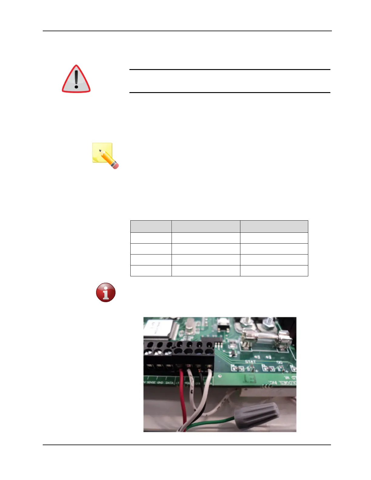
5. This step only applies if wiring to a Delayed Egress Exit Alarm
Controller - on one of the antenna ports the enclosure tamper reed
switch must be connected in series with the Sense signal using either
a crimp connector or a wire nut as shown