Chapter 1 – Installation
9450 Duolink Exit Alarm Receiver Hardware Installation Guide Page 21 of 30
0510-1103-G
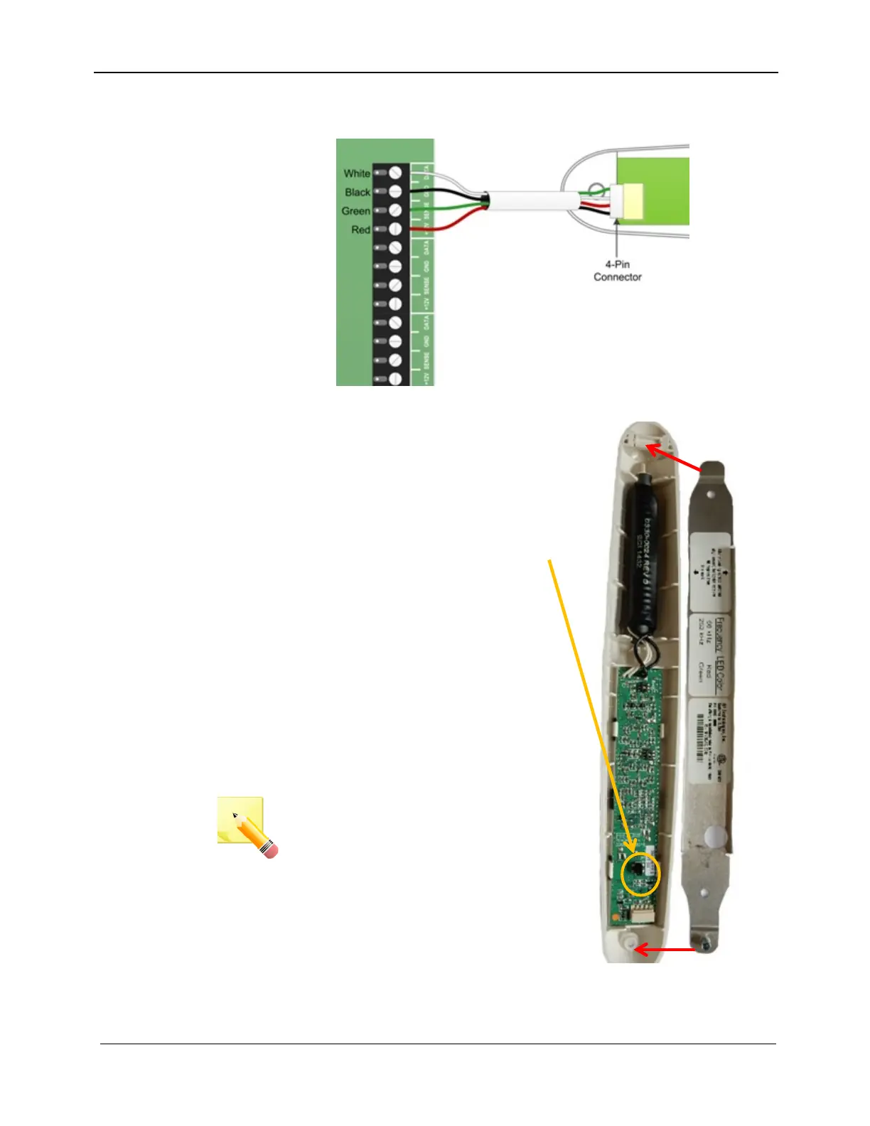
6. On the DuoLink end of the wire, plug the 4-pin connector into the
DuoLink board as shown
7. After each DuoLink has been
installed and wired to the exit
controller, close the DuoLink by
hooking one end of the DuoLink
housing onto the metal mounting
bracket and swinging the other end
into place against the opposite end
of the bracket. Once closed, this
will deactivate the Tamper Switch.
8. Secure the DuoLink housing to the
bracket with the included 5/64”
Allen head screw
9. Power the exit controller
10. Perform an antenna survey (**
9450 13 1) on the exit controller to
register the newly installed
configuration
NOTE: You must power on the exit
controller and perform an antenna
survey after the new DuoLinks
have been attached to their
brackets in order for them to
operate. (For more information
about the Antenna Survey, refer to
the Touchpad Exit Controller
Installation Guide, 0510-1100).