14
Section II :: Installation and maintenance
EN
)ROORZWKHVHLQVWDOODWLRQJXLGHOLQHV
INSTALLATION INSTRUCTIONS
!
DANGER!
,QVWDOODWLRQPXVWRQO\EHFDUULHGRXWE\VNLOOHGWHFKQLFLDQVTXDOL¿HGIRU
working on air conditioning and refrigeration systems. Incorrect instal-
lation could cause the unit to run badly, with a consequent deteriora-
tion in performance.
!
DANGER!
The unit must be installed according to national or local standards
in force at the time of installation. Always use personal protective
equipment.
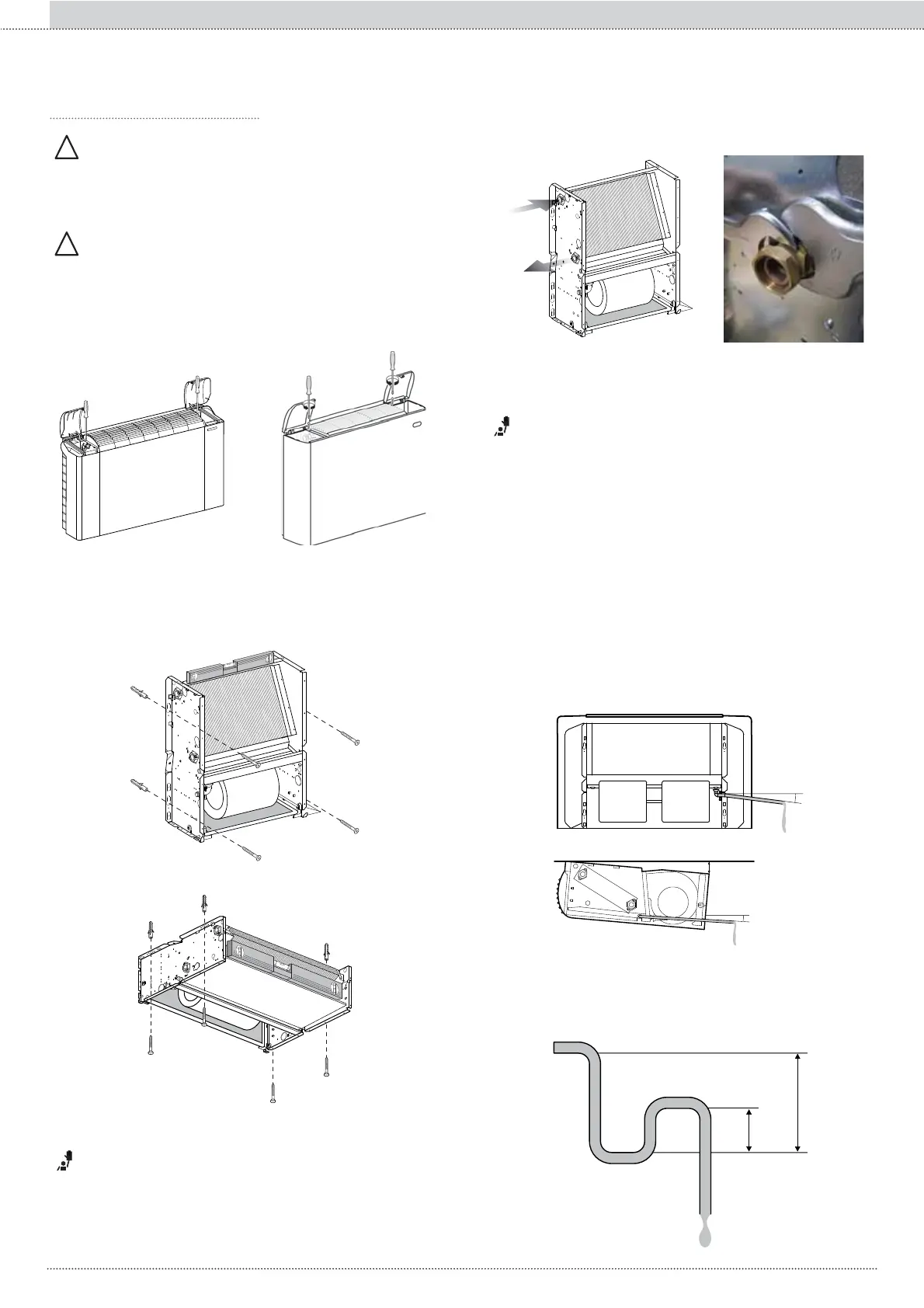
• Remove the cover panel, by loosening the screws that fasten
LWWRWKHVWUXFWXUHDVVKRZQLQ¿J
• Fasten the unit by tightening the four fastening screws in the
relative plugs.
• Mark the fastening points on the wall or ceiling using those on
the unit or referring to the values in Attachments A2. Keep a
slight tilt towards the condensate drain to help the water drain.
IMPORTANT!
It is very important for the water connections to be implemented with
JUHDWFDUHE\TXDOL¿HGSHUVRQQHO
IMPORTANT!
Water coils can be partially drained; it is recommended to bleed the air
inside the coil to be drained completely.
:DWHUFRQQHFWLRQV
6HWWLQJXSWKHFRQGHQVDWHGUDLQ
&RQQHFWLRQWRWKHV\VWHP
The condensation drainage system must be set up with an ade-
quate inclination to make sure the water comes out properly.
Hereunder are the guidelines to set up the condensate drain
correctly.
All water batteries (including the additional one), are equipped
with an air vent valve near the upper connection, and with a
water drain valve near the lower one. All the valves can be adju-
sted with a screwdriver or hex key.
Once installation is complete:
IN
OUT
• Bleed the air contained in the circuit.
• Make sure that there are no water leaks.
• Coat the valve and connection pipes with 10 mm thick anti-
condensation material or install the auxiliary pans.
• Pour water into the condensate collection pan and check that
the liquid is drained regularly, following the route up to the
condensate drain outlet. Otherwise, check the inclination and
look for possible blockages.
3 cm/m
15 mm
3 cm/m
6HWWLQJXSWKHZDWHUVLSKRQ
The condensate drain system must be set up with an adequate
VLSKRQLQRUGHUWRSUHYHQWWKHLQ¿OWUDWLRQRIRGRXUV7KHGLDJUDP
below shows how a hydraulic siphon is installed.
50 mm
100 mm
Connect the unit to the hydraulic system with the indicated inlet/
outlet connections. Make sure the connections are air tight with
the relative sealer.