2 BCD Interface Installation and Configuration Manual
2.0 Installation
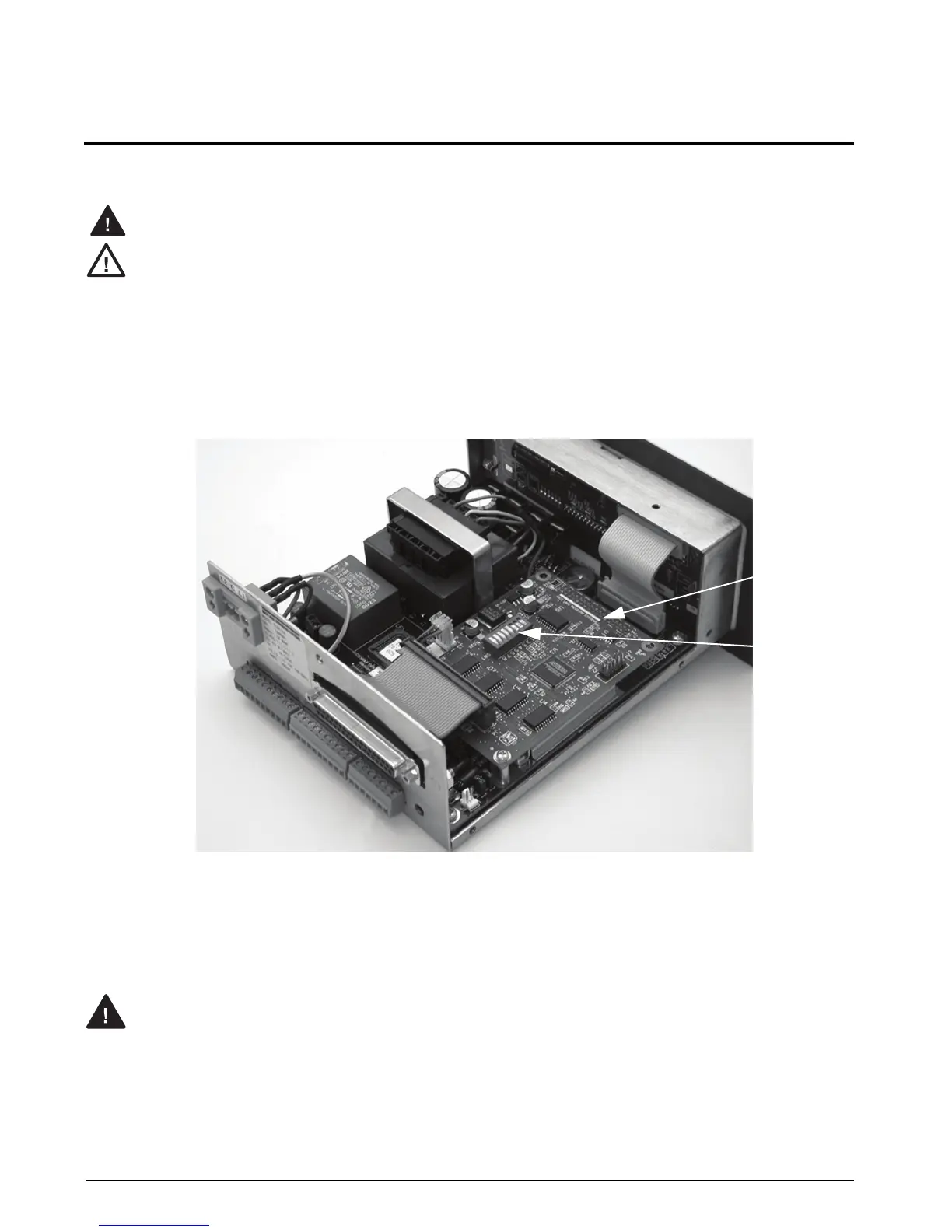
Figure 2-1 shows the BCD option card as installed in the 520 indicator. The indicator enclosure must be open to
install the BCD card.
The 520 has no on/off switch. Before opening the unit, ensure the power cord is disconnected from the
power outlet.
Use a wrist strap to ground yourself and protect components from electrostatic discharge (ESD) when
working inside the indicator enclosure.
These units use double pole/neutral fusing which could create an electric shock hazard. Procedures
requiring work inside the indicators must be performed by qualified service personnel only.
2.1 BCD Option Card Installation
1. Disconnect the 520 indicator from power source.
2. Place the indicator on an antistatic work mat. Remove screws that hold the backplate or cover to the
enclosure body, then lift the backplate or cover away from the enclosure and set it aside.
3. Use the 8-32 nuts in hardware kit to secure DB-37 connector plate to backplate of indicator.
Figure 2-1. 520 Indicator with BCD Option Installed
4. Carefully align the large option card connector (J1) with connector J2 on the 520 CPU board. Press down
to seat the option card in the CPU board connector.
5. Use the 4-40 screws provided in the option kit to secure the other end of the option card to the threaded
standoffs on the 520 CPU board.
6. Plug 40-pin ribbon cable to J4 on BCD card.
Do not connect communications to J3 if switch SW1-4 is in Units mode.
BCD Option
Board
Configuration
Dip Switch