6 BCD Interface Installation and Configuration Manual
3.0 Data Information
The following sections provide information on BCD pin-outs, data information, and remote switches.
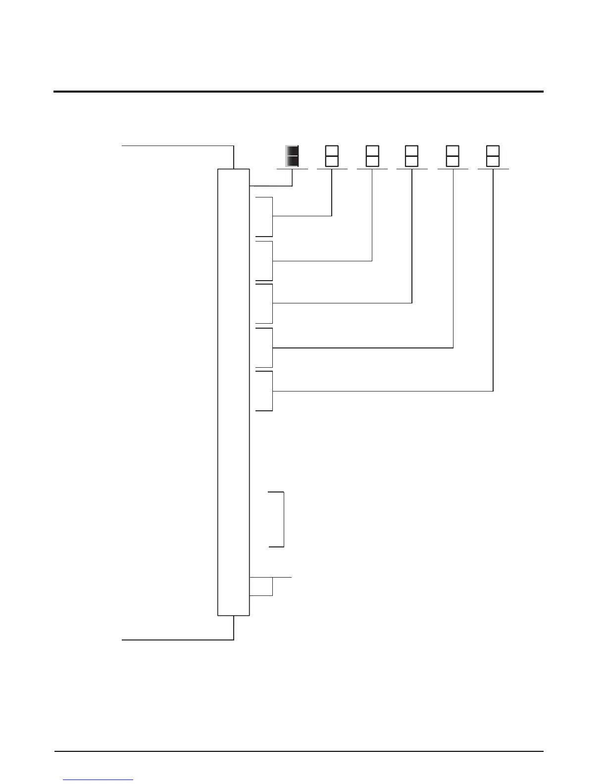
Figure 3-1. BCD External Connection
NOTE: The 520 parallel BCD option does not have a floating ground. For proper operation, it is necessary to connect Logic
Common of the BCD peripheral device to Logic Common pins 1 and 2 of the BCD option.
10
12
14
16
18
8
7
6
20
24
23
22
21
32
27
26
25
31
30
29
28
9
11
13
15
17
19
5
35
34
37
4
33
3
36
1
2
DB-37
Logic 0 = See Section 3.3 on page 10
Logic 1 = Center of Zero
Logic 1 = Valid Print
Logic 0 = Data Registers Changing
Logic 0 = Overload/Underload
Logic 0 = Scale in Motion
Logic 1 = Secondary or TX Serial Output: if dip switch configuration
Logic 1 = Net Mode is properly selected
See Figure 3-2
RX Serial Input: if dip switch configuration is properly selected.
No connect otherwise
Leading “1”
“1”
“2”
“4”
“8”
“1”
“2”
“4”
“8”
“1”
“2”
“4”
“8”
“1”
“2”
“4”
“8”
“1”
“2”
“4”
“8”
Polarity Bit
Zero Bit
Print Enable Bit
Data Valid Bit
Overload Bit
Motion Bit
Units Bit/TX Serial Output
Gross/Net Bit
Gross/Net Switch Input
Zero Switch Switch Input
Hold Switch Switch Input
Auto Tare Switch Input
Unit Select (or Tri-State Enable)
Switch Input
Serial Input
Logic Common
Logic Common
Digital Common
(Not Chassis or Earth Ground)
See note below
MSD
(Most Significant Digit)
4th SD
3rd SD
2nd SD
LSD
(Least Significant Digit)
 Loading...