pag. 26 / 57 0MNMHEM30RUENUB 00
3.4 Start-up procedure
mains power supply
The mains power supply has to be present in order to start up the MASTER HE
The MASTER HE output terminals will be powered in this phase and all applications connected will
receive voltages. All users must therefore be warned before carrying out the start-up procedure.
BATTERY CABINET if present:
The battery cabinet must be provided with a sectioning device for it to be connected to the UPS.
This disconnector must be closed only when the UPS is started up regularly. During the UPS start-up
phase the disconnector must remain in the open position.
Once the INPUT/OUTPUT and battery cables have been connected to the UPS terminals and before putting the
switch cover back in place, check that:
all the input/output terminals are securely tightened;
all the fuseholders have the fuse inserted, and are in the closed position;
the input and output protection conductor is connected correctly (yellow/green earth cable);
check the polarity of the battery connections.
Replace the switch cover.
For the first start-up, the following operations should be carried out in this order:
1) close input disconnector SWIN,
2) press button 1 twice, select the language and then press button 8 to return to the basic menu,
3) after a few seconds, messages on the status of the UPS will start to be shown on the first line of the
display panel; these will include the following message relating to the battery disconnector:
Wait: DO NOT connect the BATTERY
4) close bypass line disconnector SWBY,
5) close output disconnector SWOUT.
6) do not close the battery cabinet disconnector
Once these operations have been carried out, the humming of the fans and the sound of the buzzer will be
heard.
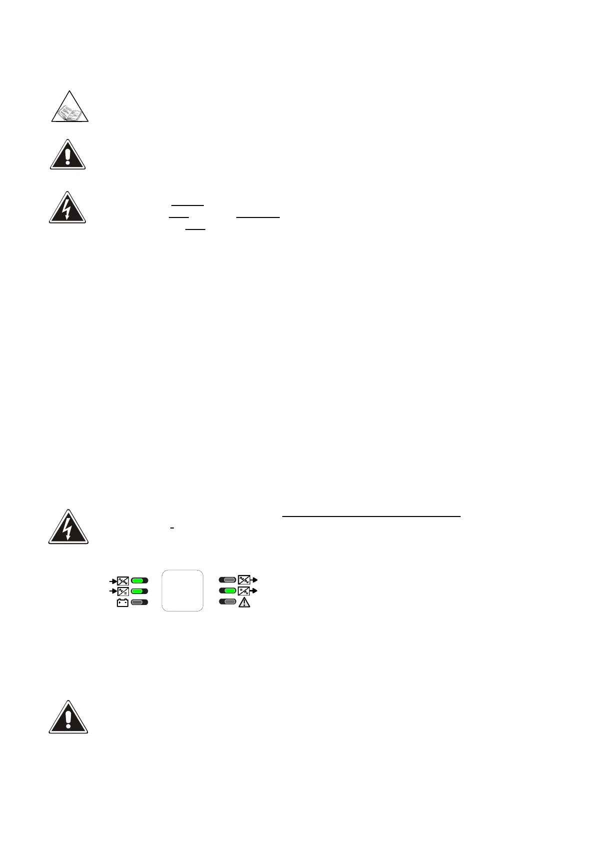
Close the battery cabinet disconnector or fuses only when the following message is shown on the first line
of the display panel:
BATTERY CHARGER OFF
Led 1 (Bypass line) on green
Led 2 (input mains) on green
Led 5 (Normal output) on green
Configure the value of the battery capacity according to the instructions on “Display and control panel”
user manual.
BATTERY CAPACITY
It is important to insert the correct battery capacity value, since this value is used by the system logic to
calculate the backup time.
If not set otherwise, this value is assumed to be equal to the UPS power. e.g. at 100kVA the value set by
default is 100Ah .