Do you have a question about the Riello UPS MULTI POWER MPX and is the answer not in the manual?
Read the safety manual before any operations on the Modular UPS System.
Explains company efforts in analysing environmental issues and product compliance.
Discusses proper disposal of toxic and dangerous waste components.
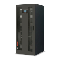
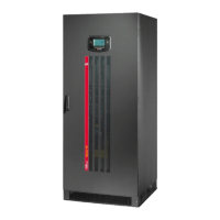
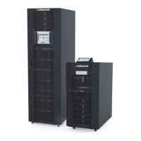
Describes the MPX modular UPS design for resilience and performance.
Details the CP, network connection and SA ports for service personnel.
Shows PSU 1 and PSU 2, optional units, and their indicators.
Details the MCU, power supply units, and communication slots.
Shows PSU 1 & 2 and Cold Start functionality.
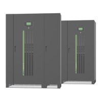
Explains the function of the Modular UPS System and its cabinet types.
Describes Normal, Battery, Automatic Static Bypass, and Eco modes.
Describes Frequency Converter and Efficiency Control modes.
Describes PMs for reliability and BM as central AUTOMATIC BYPASS.
Details minimum battery shelves required based on non-redundant PMs.
Details minimum battery shelves required based on non-redundant PMs.
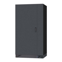
Provides a general note on cabinet installation.
Lists hot-swap modules and units for maintenance and expandability.
Shows the wiring diagram of the Bypass Module.
Explains BM's role in monitoring bypass line for backfeed and protection actions.
Explains MU's role in monitoring cabinets, PSUs, and temperatures.
Describes LEDs and Port S for the Monitoring Unit.
Details steps for inserting and extracting the MU with safety.
Shows indicators for PSU ready and supplying load.
Details steps for inserting and extracting the PSU with safety.
Describes MCU's role in monitoring, control, and communication via its display.
Details steps for inserting and extracting the MCU with safety.
Describes CP's integration of MCU/MU logic and monitoring capabilities.
Describes LEDs and Port S for the Connectivity Panel.
Details steps for inserting and extracting the CP with safety.
Details steps for inserting and extracting the BU with safety.
Explains viewing status, controlling operations, and configuring the system via display.
Explains the components of the status bar at the top of the display.
Explains the meaning of icons and their color codes for system status.
Explains how load level and redundancy are shown graphically using bars.
Shows status messages for PM, MU, BM, and cabinet alarms.
Explains the purpose of various text areas on the display interface.
Describes the function of navigation keys like Home, Previous, Send Email.
Explains the meaning of different sliding switch states (On, Off, Unavailable).
Explains symbols used in the system status display (Touch, Swipe).
Shows examples of the Home page in different operating modes (Inverter, Battery, Bypass).
Shows Home page examples for bypass, stand-by, and alarm conditions.
Explains key icons like EPO, dashed bars, and data processing indicators.
Explains how to access electrical values from the Home page.
Details measurements related to system batteries.
Details measurements related to the system bypass line.
Details measurements related to the system output.
Describes tabs for cabinets (PMs) and battery cabinets.
Shows battery cabinet status and how PM failures are indicated.
Displays general system info, localization, and network setup.
Lists system parameters set by the user, like voltage, frequency, mode.
Lists firmware versions for MU, MCU, and CP modules.
Lists serial numbers for MU and MCU modules.
Displays status and electrical values for the MPX 130 PWC power cabinet.
Displays status and electrical values for the MPX 100 CBC combo cabinet.
Displays status and electrical values for the MPW 170 BTC battery cabinet.
Shows electrical values for the PM's mains input and bypass input.
Shows electrical values and autonomy for the PM's battery.
Shows electrical values and power for the PM's output.
Displays bypass input and output values, including frequency and voltage.
Shows MU status for switches, temperature, and battery for power cabinet.
Shows status of communication slots for the MU.
Details MU status for switches, sensors, and slots in a combo cabinet.
Details MU status for switches, sensors, and batteries in a battery cabinet.
Displays electrical values and anomalies within a selected Battery Unit Array.
Explains the different user access levels (User, PowerUser, Expert) and their capabilities.
Explains that Power User access is required for the Command Panel.
Details the steps to switch the system ON using the Command Panel.
Describes the sequence for system start-up after the ON command.
Explains how to perform a cold start from the battery.
Explains how to execute a battery test via the Command Panel.
Explains how to switch individual power modules on or off.
Describes how to view the system event log file.
Describes how to view the communication status of the system.
Details how to export log files to a USB drive.
Explains how to restore operation after an EPO condition.
Enables the language configuration of system menus.
Allows configuration of date, time, and NTP synchronization.
Enables scheduling of automatic battery tests and email logs.
Displays available languages for system menus.
Allows setting the date, time, and timezone of the system.
Enables regular system clock synchronization with an NTP server.
Configures scheduling for automatic battery tests.
Programs logs to be sent via email daily or weekly.
Configures SMTP client details like server name, port, and sender email.
Sets up email addresses for system event messages, filterable by alarm category.
Configures the text for email subject, header, and footer.
Sets hostname, IP address, netmask, gateway, and DNS.
Configures UDP, HTTP, and SSH services with ports and passwords.
Configures system name, location, and contact person.
Allows setting or changing passwords for User, PowerUser, and Expert levels.
Defines inactivity period for homepage display and energy saving, and activates the buzzer.
Describes different modulated sounds emitted by the buzzer for UPS status.
Reminds to close SWMBs simultaneously to avoid excess loads.
Explains consistency tests performed by MCU/CP during start-up.
Shows cabinet type selection screen on hardware/software setting discrepancies.
Describes system state of "partial switching on" during EPO and how to exit.
Details optional kits like dust filter, temperature sensor, parallel communication, redundant PSU, and IPX1 protection.
Describes expansion slots for communication or I/O cards.
Explains backfeed protection options and cold start functionality.
Describes the Connectivity Panel's interface, slots, and Ethernet port.
Explains UDP, HTTP, and SMTP protocols for system control and monitoring.
Shows screenshots of monitoring via web browser, including dashboard and data views.
Describes accessing a special page for simplified monitoring via web interface.
Explains SNMP and Modbus TCP protocols with Netman 204 card.
Explains Modbus 485 protocol with MultiCOM 302 card.
Details steps to switch the system ON using a direct command.
Details steps to switch the system ON via static bypass.
Steps to switch to manual bypass using static bypass.
Steps for direct manual bypass, which is not recommended.
Steps to switch the system back to normal operation from manual bypass.
Procedure for replacing a Power Module when redundancy is available.
Procedure for replacing a Power Module when redundancy is not available.
Procedure for replacing a Bypass Module during online mode.
Details procedures for replacing MU, MCU, CP, and PSU units.
Procedure for replacing a Battery Unit, must not be in battery mode.
Lists MPX system status messages and their severity.
Lists Power Module status messages and their severity.
Lists alarm codes for PM commands, warnings, and anomalies.
Lists alarm codes for PM faults.
Lists alarm codes for PM locks.
Lists BM status messages and alarm codes for commands, warnings, anomalies, faults, locks.
Lists MU status messages and alarm codes for commands, anomalies, faults, and BU alarms.
Emphasizes regular checks for electronic power equipment and component life limits.
States personnel requirements and discusses battery maintenance considerations.
Explains the importance of preventive maintenance for cooling systems and capacitors.
Lists input, bypass, and output voltage, frequency, power factor, and overload specs.
Details battery configuration, characteristics, cabinet types, dimensions, and noise level.
Lists storage temp, humidity, installation height, pollution, vibration, and safety standards.
| Transfer Time | 0 ms |
|---|---|
| Input Voltage | 400 V (3Ph+N) |
| Output Voltage | 400 V (3Ph+N) |
| Frequency | 50/60 Hz |
| Topology | Double Conversion Online |
| Form Factor | Tower/Rackmount |
| Efficiency | Up to 96% |
| Scalability | Modular |
| Parallel Capability | Up to 8 units |
| Battery Type | VRLA |
| Communication | RS232, USB, SNMP |
| Operating Temperature | 0°C to 40°C |
| Weight | Dependent on configuration |