‐26‐
INSERTION/EXTRACTION PROCEDURE
The following operations must only be performed by skilled and specifically trained personnel.
When the BM is not inserted, uncovered parts with dangerous voltage are present within the corresponding
backplane.
The BM, due to its weight, must be handled by two people.
The BM is pre-installed by the manufacturer, extract it only in case of maintenance or replacement.
Strictly comply with the instructions as listed below.
EXTRACTION
WARNING: Before performing the operations below, ensure that the shutting of the BM does not lead to the loss of the
connected load.
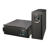
1. Turn the Switch Lock 90 degrees anticlockwise to the open position (see the
picture on the right).
2. Wait until the front LEDs switch off.
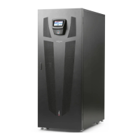
3. Remove the two side fastening screws and
store them.
4. Carefully extract the BM from its housing. This
operation requires two persons.
5. Caution: when the BM is not inserted, uncovered parts with dangerous voltage are present on the corresponding
backplane. Therefore, in the case where a new BM is not immediately inserted, install the supplied protection cover using
the dedicated screws.
INSERTION
1. If present, remove the protection cover and store it together with the fastening screws.
2. Check that the Switch Lock is in open position (see the picture on the right).
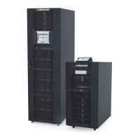
3. Carefully insert the BM into the cabinet (requires two
persons) and fasten it using the supplied screws, as
shown in the picture.
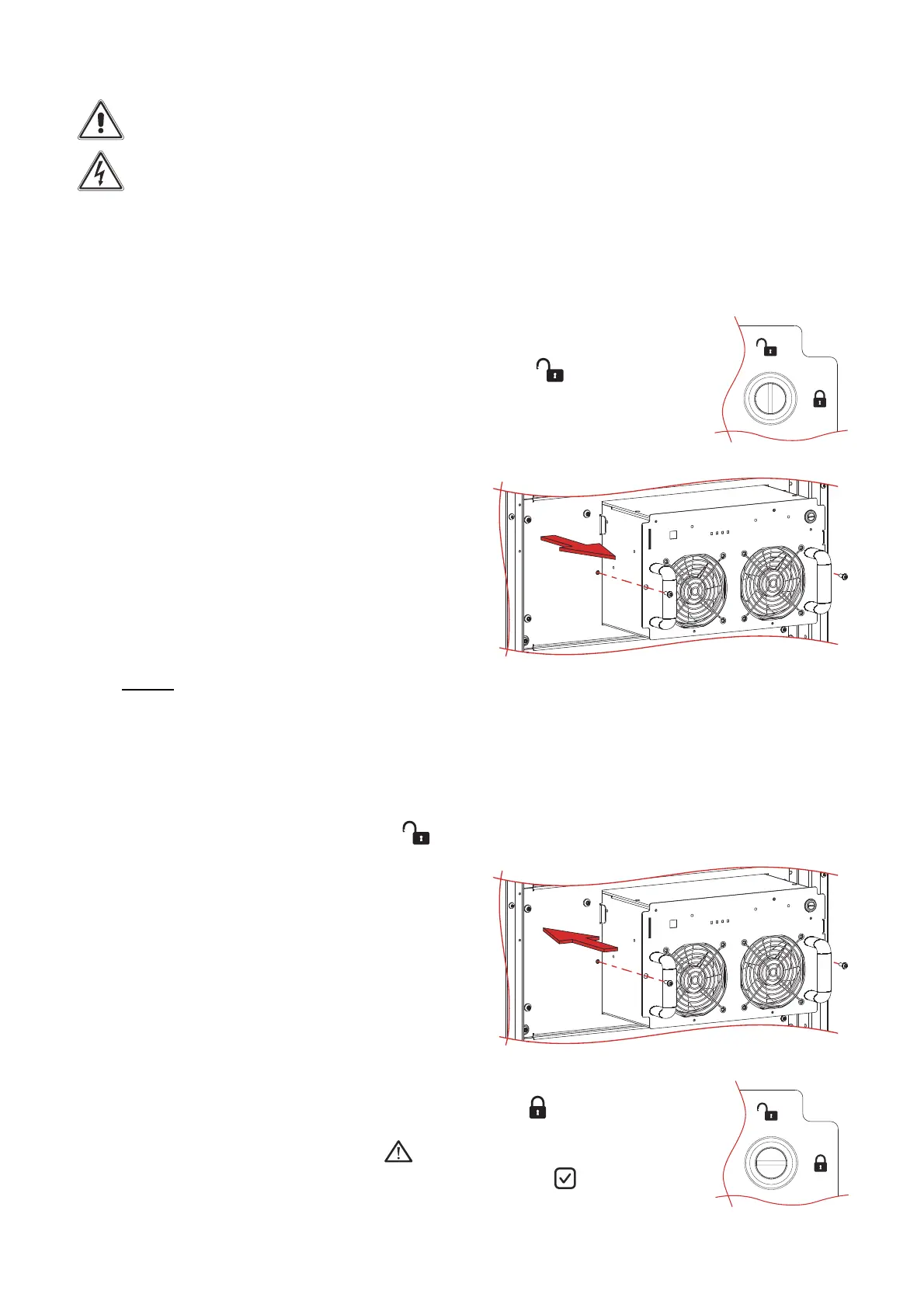
4. Turn the Switch Lock 90 degrees clockwise to the closed position
(see the picture on the right).
During the first start-up, the red alarm LED will blink for 10 s, after which, if the start-
up was successful, the green normal operation LED will change to on .