‐23‐
INSERTION/EXTRACTION PROCEDURE
The following operations must only be performed by skilled and specifically trained personnel.
When the PM is not inserted, uncovered parts with dangerous voltage are present within the corresponding
backplane.
The PM, due to its weight, must be handled by at least two persons.
Strictly comply with the instructions as listed below.
INSERTION
1. Note: the PM must be inserted in the slot of
a previously removed one or, in case of first
installation, in the first free dedicated slot of
the cabinet, starting from the bottom slot.
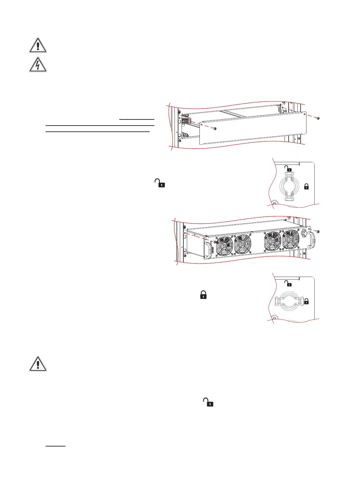
If present, remove the protection cover and
store it together with the fastening screws.
2. Check that the Switch Lock is in open position (see the picture on the right).
3. Carefully insert the PM into the cabinet
(requires two persons) and fasten it using the
supplied screws, as shown in the picture.
4. Turn the Switch Lock 90 Degrees clockwise to the closed position
(see the picture on the right).
5. Switch on the PM using the display (ref. to “Operative procedures” chapter).
EXTRACTION
Note: before extracting any PM, please ensure that the remaining PMs are capable of supporting the full
load.
To extract the PM from the cabinet, reverse the procedure described above. In brief:
1. Switch off the PM using the display (ref. to “Operative procedures” chapter).
2. Turn the Switch Lock 90 degrees anticlockwise to the open position .
3. Wait until the front LEDs switch off.
4. Remove the two side fastening screws and store them.
5. Carefully extract the PM from its housing. This operation requires two persons.
6. Caution: when the PM is not inserted, uncovered parts with dangerous voltage are present on the corresponding
backplane. Therefore, in the case where a new PM is not immediately inserted, install the supplied protection cover using
the dedicated screws.