‐22‐
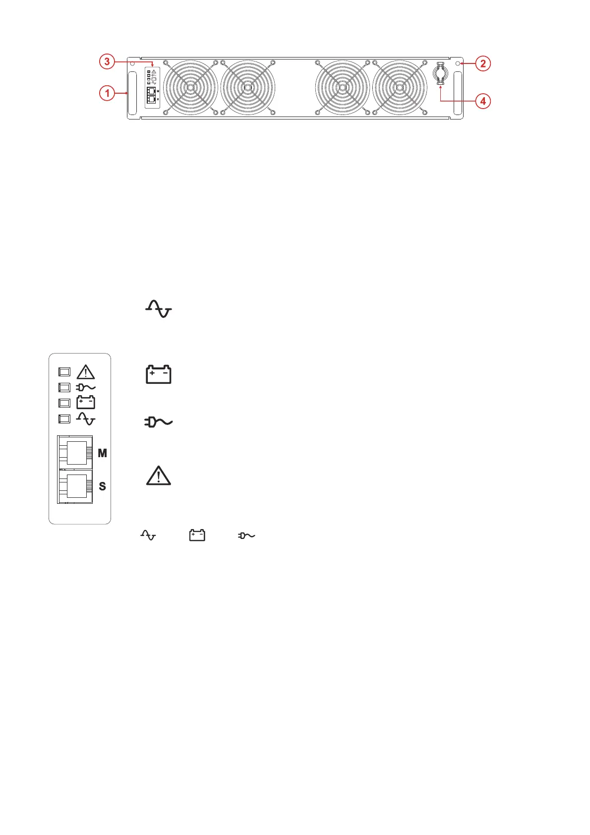
①
Handles for inserting and extracting the cabinet
③
Interface panel
②
Holes for fastening the PM to the cabinet using the
specific screws
④
Switch Lock: rotating switch and mechanical
lock for the PM into the cabinet
INTERFACE PANEL
Green
Mains operation LED
On steady: mains operation with a good bypass line and synchronised inverter
Slow blinking:
- 500 ms ON - 800 ms OFF: mains operation with bad or disabled bypass line and/or
non-synchronised inverter.
- 130 ms ON - 2.5 s OFF: module in EFFICIENCY CONTROL mode
Yellow
Battery operation LED
On steady: battery operating mode
Slow blinking: battery operation with early low battery or imminent shutdown warning
Green
Load on bypass LED
On steady: load powered from bypass line
Slow flashing: load fed by inverter while waiting to return to bypass (Eco mode)
Red
Standby/alarm LED
On steady: alarm present
Slow blinking: Stand-by mode
Fast blinking: awaiting address from MCU of CP
+
+
Slow blinking: Start-up
M
S
Communication ports reserved for service personnel only